Details of LED connection methods
In our life, LEDs confidently crowd out other sources of artificial light from lighting technology. But if incandescent lamps can be connected directly to the power supply, then the connection of the LED and discharge lamps requires special measures.
At the same time, connecting a single LED does not cause problems. And turning on from a few units to hundreds is not as easy as it seems.
A bit of theory
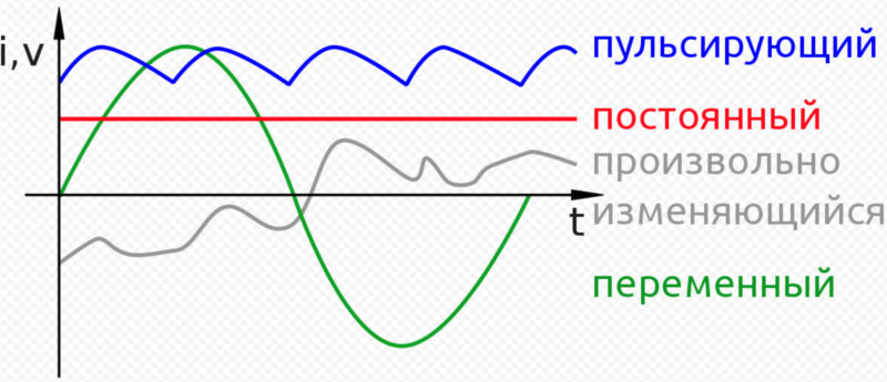
An LED requires a constant voltage or current to operate properly. They should be:
- Constant in direction. That is, the current in the LED circuit, when voltage is applied, must flow from the "+" voltage source to its "-".
- stable, i.e. constant in magnitude, during the operation of the diode.
![Details of LED connection methods]()
- Not pulsating - after rectification and stabilization, the values \u200b\u200bof constant voltage or current should not change periodically.
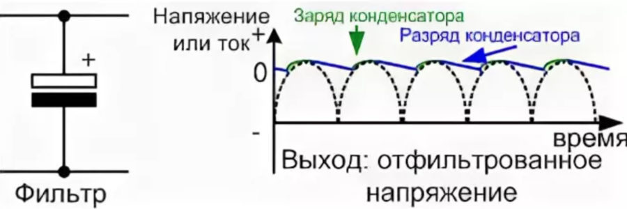
![Voltage waveform diagram]() Scheme of the voltage shape at the output of a full-wave rectifier when filtered by an electrolytic capacitor (black and white rectangles marked "+" in the diagram). The dotted line is the voltage at the rectifier output. The capacitor is charged to a half-wave amplitude and gradually discharges at the load resistance. "Steps" are pulsations. The ratio of the step and half-wave amplitudes in percent is the ripple factor.
Scheme of the voltage shape at the output of a full-wave rectifier when filtered by an electrolytic capacitor (black and white rectangles marked "+" in the diagram). The dotted line is the voltage at the rectifier output. The capacitor is charged to a half-wave amplitude and gradually discharges at the load resistance. "Steps" are pulsations. The ratio of the step and half-wave amplitudes in percent is the ripple factor.
For LEDs at first, the available voltage sources were used - 5, 9, 12 V. And the operating voltage of the p-n junction is from 1.9-2.4 to 3.7-4.4 V. Therefore, turning on the diode directly is almost always its physical combustion from overheating with a large current. current need limit with a current-limiting resistor, spending energy to heat it.
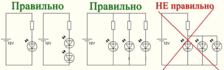
LEDs can be switched on in series in several pieces. Then, by assembling a chain of them, it is possible, by the sum of their forward voltages, to reach almost the voltage of the power source. And the remaining difference is "repaid" by dissipating it in the form of heat on the resistor.
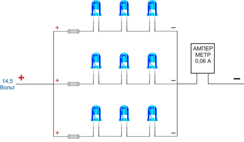
When there are dozens of diodes, they are connected in series circuits, which are connected in parallel.
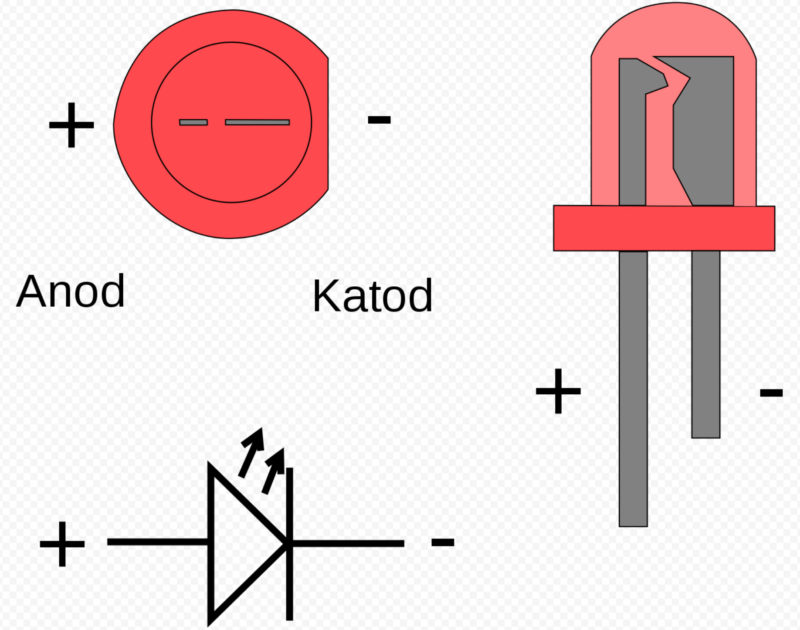
LED pinout
LED polarity - anode or plus and cathode - minus is easy to determine from the pictures:
LED switching circuit
The LED is powered by constant voltage. But the features of the nonlinear dependence of its internal resistance require that the operating current be kept within narrow limits. At a current less than the rated, it decreases light flow, and at a higher value, the crystal overheats, the brightness of the glow increases, and the "life" is reduced. The simplest way to extend it is to limit the current through the crystal by including a current-limiting resistor. For powerful LEDs, this is economically unprofitable, because they are fed with direct current from a special source of stable current - drivers.
serial connection
An LED is a fairly complex lighting device. It works from a secondary source of direct voltage. With a power of more than 0.2-0.5 W, most LED devices use current sources. They are not entirely correct, in the American manner, called drivers. When diodes are connected in series, power supplies with a voltage of 9, 12, 24, and even 48 V are often used. In this case, a series chain is built, in which there can be from 3-6 to several tens of elements.
When connected in series in a chain, the anode of the first LED is connected through a current-limiting resistor to the “+” of the power source, and the cathode is connected to the anode of the second. And so the whole chain is connected.
For example, red LEDs have a forward operating voltage of 1.6V to 3.03V. Uetc. = 2.1 V one LED on the resistor at a source voltage of 12 V will have a voltage of 5.7 V:
12V - 3x2.1V = 12 - 6.3 = 5.7V.
And already 3 consecutive chains are connected in parallel.
Table of direct voltage on the LED from the color of its glow.
| Glow color | Operating voltage, direct, V | Wavelength, nm |
|---|---|---|
| White | 3,5 | Wide spectrum |
| Red | 1,63–2,03 | 610-760 |
| Orange | 2,03–2,1 | 590-610 |
| Yellow | 2,1–2,18 | 570-590 |
| Green | 1,9–4,0 | 500-570 |
| Blue | 2,48–3,7 | 450-500 |
| Violet | 2,76–4 | 400-450 |
| Infrared | up to 1.9 | from 760 |
| UV | 3,1–4,4 | up to 400 |
With a series connection of LEDs, the currents through the LEDs will be the same, and the drop on each element is individual. It depends on the internal resistance of the diode.
Serial connection properties:
- the breakage of one element leads to the shutdown of all;
- shorting - redistributes its voltage to all the remaining ones, the brightness of the glow increases on them and degradation accelerates.
Recommended: How to find out how many volts an LED
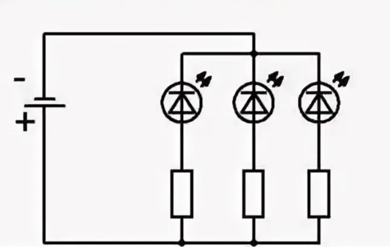
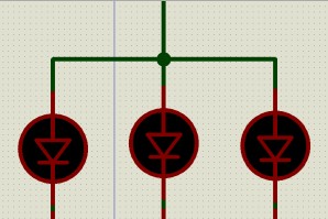
Parallel connection
In this LED connection scheme, all anodes are connected to each other and to the “+” of the power source, and cathodes to “-”.
Such a connection was on the first LED garlands, rulers and ribbons when powered by a voltage of 3-5 V.
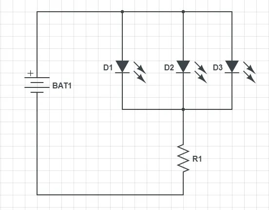
If a burnout occurs with the closing of the p-n junction, then the entire battery voltage will be applied to the resistor R1. It will overheat and burn out.
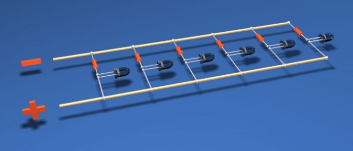
On the picture:
- gray stripes - current-carrying tires, i.e. wires without insulation;
- blue cylinders with a rounded end - cylindrical LEDs with a lens on the end;
- red - resistors to limit the operating current.
It will be incorrect to connect all diodes to one resistor. Due to the scatter in the characteristics of LEDs, even in one batch that can reach from 50 to 200% or more, a current can flow through the diodes, which will vary significantly. Therefore, they will also glow and load differently. Later, the most loaded, glowing brighter than others, will burn out or degrade to almost complete attenuation, losing 70-90% of the luminous flux. Or change the tint of the glow from white to yellow.
mixed
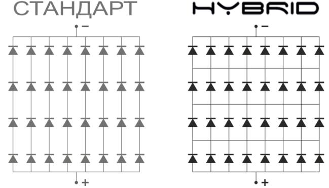
A combined or mixed connection is used when creating LED matrices consisting of many tens or hundreds of elements or unpackaged crystals. The most famous of them are COB matrices.
The supply voltage and operating current with combined switching on will be less than the rated operating ones. Only under this condition, the matrix will work more or less for a long time. At rated current, the weakest link will quickly burn out and the rest will gradually burn out. It will end with breaks in serial chains and shorting of parallel ones.
Connecting a light emitting diode to a 220 V network
If you power the LED directly from 220 V with a current limit, then it will shine with a positive half-wave and go out with a negative one. But this is only in the case when the reverse voltage of the p-n junction is much more than 220 V. Usually it is in the region of 380-400 V.
The second way to turn on is through a quenching capacitor.
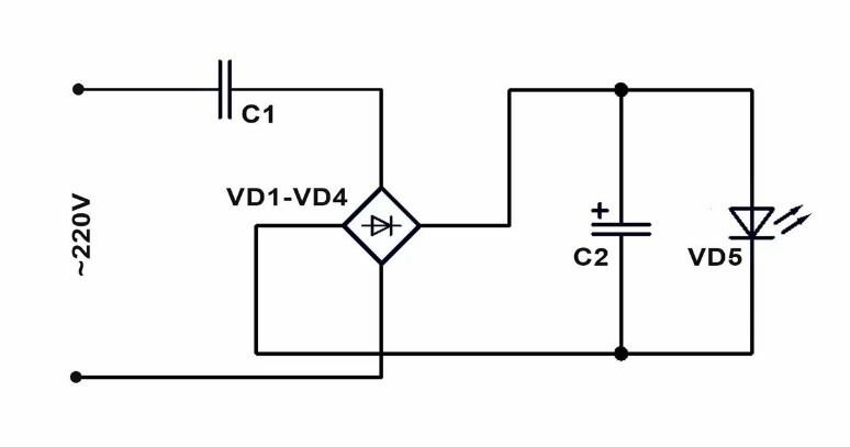
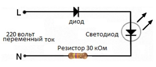
ATTENTION! Most circuits with direct connection to the 220 V network have a serious drawback - they are dangerous for human injury with high voltage - 220 V. Therefore, they should be used carefully, with careful isolation of all current-carrying parts.
Detailed information on connecting the LED to a 220 V network described here.
How to power diodes from a power supply
The most popular transformerless switching power supplies (PSU) provide 12 V with protection for current, short circuit, overheating, etc.
Therefore, the LEDs are connected in series and limit their current with a conventional resistor. The chain includes 3 or 6 diodes. Their number is determined by the forward voltage of the diode. Their sum for current limitation should be less than the output voltage of the PSU by 0.5-1 V.
Features of connecting RGB and COB LEDs
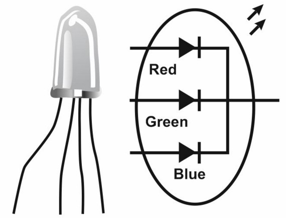
LEDs with abbreviation RGB - These are polychrome or multi-color light emitters of different colors. Most of them are assembled from three LED crystals, each of which emits a different color.Such an assembly is called a color triad.
Connecting an RGB LED is done in the same way as conventional LEDs. In each case of such a multi-color light source, there is one crystal: Red - red, Green - green and Blue - blue. Each LED has its own operating voltage:
- blue - from 2.5 to 3.7 V;
- green - from 2.2 to 3.5 V;
- red - from 1.6 to 2.03 V.
Crystals can be connected to each other in different ways:
- with a common cathode, i.e., three cathodes are connected to each other and with a common terminal on the case, and the anodes each have their own terminal;
- with a common anode - respectively, for all anodes, the output is common, and the cathodes are individual;
- independent pinout - each anode and cathode has its own output.
Therefore, the values of the current-limiting resistors will be different.
In both cases, the diode housing has 4 wire leads, pads in SMD LEDs or a pin in the piranha housing.
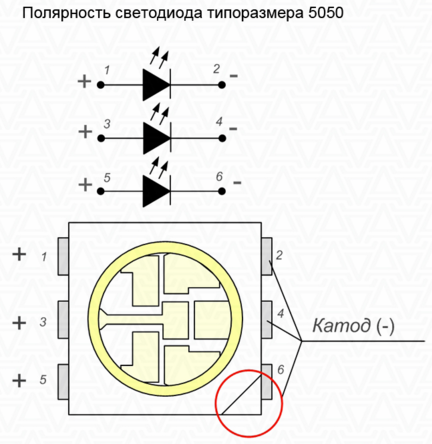
In the case of independent LEDs, there will be 6 outputs.
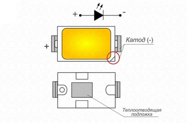
In case SMD 5050 LED crystals are arranged as follows:
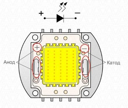
Connecting COB LEDs
The abbreviation COB is the first letters of the English phrase chip-on-board. In Russian, it will be - an element or a crystal on the board.
The crystals are glued or soldered onto a heat-conducting sapphire or silicon substrate. After checking the correct electrical connections, the crystals are filled with a yellow phosphor.
COB LEDs - these are matrix structures consisting of tens or hundreds of crystals, which are connected in groups with a combined inclusion of semiconductor p-n junctions. Groups are sequential chains of LEDs, the number of which corresponds to the supply voltage of the LED matrix. For example, at 9 V these are 3 crystals, 12 V - 4.
Chains connected in series are connected in parallel. Thus, the required power of the matrix is gained. Blue glow crystals are filled with yellow phosphor. It re-radiates blue light to yellow, making it white.
Light quality, i.e. color rendering regulate in the production process the composition of the phosphor. One- and two-component phosphor gives low quality, because it has 2-3 emission lines in the spectrum. Three- and five-component - quite acceptable color reproduction. It can be up to 85-90 Ra and even higher.
Connecting this type of light emitters does not cause problems. They are switched on as a normal powerful LED, powered by a standard current source. For example, 150, 300, 700 mA. The manufacturer of COB matrices recommends choosing current sources with a margin. It will help when putting a luminaire with a COB matrix into operation.