How to make a 12 volt power supply with your own hands - examples of circuits
A 12 volt DC power supply is a useful device for a home, cottage or garage. Such a device is easy to make yourself. Below is a diagram of a 12V power supply for do-it-yourself assembly, as well as tips on calculating and choosing components.
Types of power supplies
To date, pulsed voltage sources have become widespread. They have a significant advantage over traditional transformer circuits in terms of energy efficiency and weight and size. It is believed that at load currents of more than 5 amperes, they have undeniable preferences. But they also have disadvantages - for example, the generation of RF interference into the supply network and into the load.And the main obstacle for home assembly is the complexity of the circuits and the need for special skills for the manufacture of winding parts. Therefore, it is better for a medium-skilled home master to manufacture a power supply according to the usual principle with a network step-down transformer.
Where is the voltage source used
The scope of such a PSU in the household is wide:
- power supply of low-voltage lamps;
- battery charging;
- power supply for audio devices.
As well as many other purposes that require a constant voltage of 12 volts.
Scheme of a transformer power supply
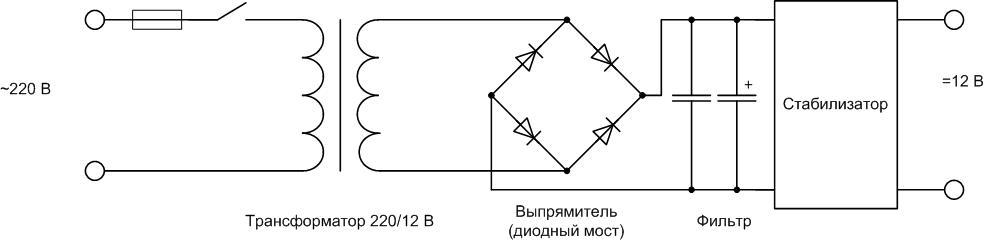
A 12 volt power supply circuit operating from a 220 V network consists of the following nodes:
- A step-down transformer. It consists of iron, primary and secondary (there may be several) windings. Without going deep into the principle of operation, it should be noted that the output voltage depends on the ratio of turns of the primary (n1) and secondary (n2) windings. To obtain 12 volts, it is necessary that the secondary winding contains 220/12 = 18.3 times fewer turns than the primary.
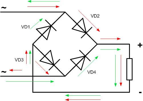
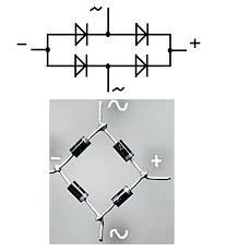
- Rectifier. Most often performed in the form of a full-wave circuit (diode bridge). Converts alternating voltage to pulsating. The current passes through the load twice in the same direction.
![How to make a 12 volt power supply with your own hands - examples of circuits]() The operation of a full-wave rectifier.
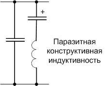
The operation of a full-wave rectifier. - Filter. Converts pulsating voltage to DC. It charges when voltage is applied, and discharges during pauses. It consists of a high-capacity oxide capacitor, in parallel with which a ceramic capacitor with a capacity of about 1 μF is often connected. To understand the need for this additional element, it must be remembered that the oxide capacitor is arranged in the form of foil strips rolled into a roll.This roll has parasitic inductance, which significantly degrades the quality of high-frequency noise filtering. To do this, an additional capacitor for shorting the RF pulses is switched on.
![How to make a 12 volt power supply with your own hands - examples of circuits]() Equivalent circuit of the filter with oxide and additional capacitors.
Equivalent circuit of the filter with oxide and additional capacitors. - Stabilizer. May be missing. Schemes of simple but effective nodes are discussed below.
The following sections discuss how to select and calculate each element of a 12 volt DC source.
Transformer selection
There are two ways to obtain a suitable transformer. Independent production of a step-down block and selection of a suitable one in the factory. In any case, keep in mind:
- at the output of the step-down winding of the transformer, when measuring the voltage, the voltmeter will show the effective voltage (1.4 times less than the amplitude);
- on the filter capacitor without load, the constant voltage will be approximately equal to the amplitude (they say that the voltage on the capacitor “rises” by 1.4 times);
- if there is no stabilizer, then under load the voltage on the capacitance will drop depending on the current;
- for the stabilizer to work, a certain excess of input voltage over the output voltage is required, their ratio limits the efficiency of the power supply as a whole.
From the last two points, it follows that for normal operation of the PSU, the voltage of the transformer must exceed 12 V.
Self-winding transformer
The full calculation and manufacture of a home-made power transformer is complex, time-consuming, requires tools and skills. Therefore, a simplified path will be considered - the selection of a block suitable for iron and altering it to 12 V.
If there is a ready-made transformer, but there is no diagram of its connection, you need to call its winding tester with a tester.The winding with the highest resistance is likely to be mains. The rest of the windings must be removed.
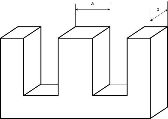
Next, you need to measure the thickness of the iron set b and the width of the central plate a and multiply them. The cross-sectional area of \u200b\u200bthe core is obtained S \u003d a * b (in sq. cm). It determines the power of the transformer P=![]() . Next, the maximum current in amperes is calculated, which can be removed from a winding with a voltage of 12 volts: I \u003d P / 12.
. Next, the maximum current in amperes is calculated, which can be removed from a winding with a voltage of 12 volts: I \u003d P / 12.
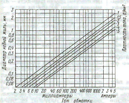
Next, the number of turns per volt is calculated using the formula n=50/S. For 12 volts, it is necessary to wind 12 * n turns with a margin of about 20% for losses in copper and on the stabilizer. And if not, then the voltage drop under load. And the last step is to select the cross section of the winding wire according to the graph for a current density of 2-3 mA / sq. mm.
For example, there is a transformer with a primary winding of 220 V with a set of iron 3.5 cm thick and a middle tongue width of 2.5 cm. Hence, S = 2.5 * 3.5 = 8.75 and the power of the transformer ![]() =3 W (approximately). Then the maximum possible current at 12 volts is I=P/U=3/12=0.25 A. For winding, you can choose a wire with a diameter of 0.35..0.4 sq. mm. For 1 volt there are 50 / 8.75 = 5.7 turns, it is necessary to wind 12 * 5.7 = 33 turns. Taking into account the stock - about 40 turns.
=3 W (approximately). Then the maximum possible current at 12 volts is I=P/U=3/12=0.25 A. For winding, you can choose a wire with a diameter of 0.35..0.4 sq. mm. For 1 volt there are 50 / 8.75 = 5.7 turns, it is necessary to wind 12 * 5.7 = 33 turns. Taking into account the stock - about 40 turns.
Selection of a finished transformer
If there is a ready-made transformer with a secondary winding suitable for current and voltage, you can try to pick up a ready-made one. For example, in the CCI series there are suitable products with a secondary winding voltage close to 12 volts.
| Transformer | Designation of the conclusions of the secondary winding | Voltage, V | Permissible current, A |
| Chamber of Commerce and Industry48 | 11-12, 13-14, 15-16, 17-18 | 13,8 | 0,27 |
| CCI209 | 11-12, 13-15 | 11,5 | 0,0236 |
| CCI216 | 11-12, 13-14, 15-16, 17-18 | 11,5 | 0,072 |
The advantage of this solution is the minimum labor intensity and reliability of factory execution. Minus - the transformer contains other windings, the overall power is also calculated for their load.Therefore, in terms of weight and size, such a transformer will lose.
Diode selection and rectifier fabrication
Diodes in the rectifier are selected according to three parameters:
- the highest allowable forward voltage;
- the highest reverse voltage;
- maximum operating current.
According to the first two parameters, 90 percent of the available semiconductor devices are suitable for operation in a 12-volt circuit, the choice is mainly made by the maximum continuous current. The design of the diode case and the method of manufacturing the rectifier also depend on this parameter.
If the load current does not exceed 1 A, foreign and domestic one-ampere diodes can be used:
- 1N4001-1N4007;
- HER101-HER108;
- KD258 (“droplet”);
- KD212 and others.
For lower currents (up to 0.3 A), KD105 (KD106) devices are designed. All of the listed diodes can be mounted both vertically and horizontally on a printed circuit or circuit board, or simply on pins. They don't need radiators.
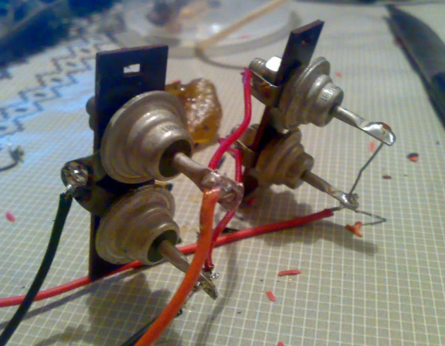
If you need large operating currents, then you need to use other diodes (KD213, KD202, KD203, etc.). These devices are designed for operation on heat sinks, without them they will withstand no more than 10% of the maximum nameplate current. Therefore, you need to choose ready-made heat sinks or make them yourself from copper or aluminum.
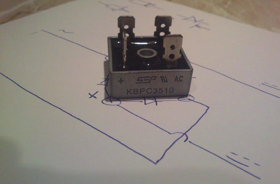
It is also convenient to use ready-made bridge diode assemblies KTS405, KVRS or the like. They do not need to be assembled - it is enough to apply an alternating voltage to the corresponding outputs and remove the constant.
Capacitor capacity
The capacitance of a capacitor depends on the load and on the ripple it allows.To accurately calculate the capacity, there are formulas and online calculators that can be found on the Internet. For practice, you can focus on the numbers:
- at low load currents (tens of milliamps), the capacitance should be 100..200 uF;
- at currents up to 500 mA, a 470..560 uF capacitor is needed;
- up to 1 A - 1000..1500 uF.
For higher currents, the capacitance increases proportionally. The general approach is that the larger the capacitor, the better. You can increase its capacity to any limits, limited only by size and cost. In terms of voltage, it is necessary to take a capacitor with a serious margin. So, for a 12-volt rectifier, it is better to take a 25-volt element than a 16-volt one.
These considerations are true for unstabilized sources. For a PSU with a capacity stabilizer, it can be reduced by several times.
Output voltage stabilization
A stabilizer at the output of the power supply is not always needed. So, if it is supposed to use a power supply unit in conjunction with sound-reproducing equipment, then the output must have a stable voltage. And if the heating element serves as the load, the stabilizer is clearly redundant. For LED strip power supply you can do without the most complex power supply module, but on the other hand, a stable voltage ensures the independence of the brightness of the glow during power surges and extends the life of the LED lamp.
If the decision to install a stabilizer is made, then the easiest way is to assemble it on a specialized LM7812 chip (KR142EN5A). The switching circuit is simple and does not require adjustment.
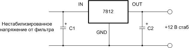
Voltage from 15 to 35 volts can be applied to the input of such a stabilizer. A capacitor C1 with a capacity of at least 0.33 microfarads must be installed at the input, at least 0.1 microfarads at the output.The capacitor of the filter block usually acts as C1 if the length of the connecting wires does not exceed 7 cm. If this length cannot be maintained, then a separate element will need to be installed.
Chip 7812 has protection against overheating and short circuit. But she does not like polarity reversal at the input and the supply of external voltage to the output - her time in life in such situations is calculated in seconds.
Important! For load current over 100 mA, the installation of an integral stabilizer on a heat sink is mandatory!
Increasing the output current of the stabilizer
The above circuit allows you to load the stabilizer with a current of up to 1.5 A. If this is not enough, you can power the node with an additional transistor.
Circuit with an n-p-n structure transistor
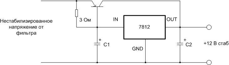
This circuit is recommended by the developers and is included in the datasheet for the chip. The output current must not exceed the maximum collector current of the transistor, which must be provided with a heat sink.
P-n-p transistor circuit
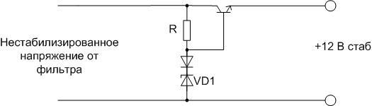
If there is no semiconductor triode of the n-p-n structure, then the stabilizer can be boosted with a p-n-p semiconductor triode.
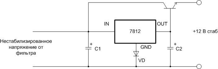
A low-power silicon diode VD increases the output voltage of the 7812 by 0.6 V and compensates for the voltage drop at the emitter junction of the transistor.
Parametric Stabilizer
If for some reason an integrated regulator is not available, you can run a node on a zener diode. It is necessary to choose a zener diode with a stabilization voltage of 12 V and designed for the appropriate load current. The highest current for some 12-volt domestic and imported zener diodes is indicated in the table.
| Zener type | D814G | D815D | KS620A | 1N4742A | BZV55C12 | 1N5242B |
| Load current | 5 mA | 0.5 A | 50 mA | 25 mA | 5 mA | 40 mA |
| Stabilization voltage | 12 volt | |||||

The resistor value is calculated by the formula:
R \u003d (Uin min-Ust) / (In max + Ist min), where:
- Uin min - minimum input unstabilized voltage (should be at least 1.4 Ust), volts;
- Ust - stabilization voltage of the zener diode (reference value), volt;
- In max - the highest load current;
- Ist min - minimum stabilization current (reference value).
If there is no zener diode for the desired voltage, it can be made up of two connected in series. In this case, the total voltage should be 12 V (for example, D815A at 5.6 volts plus D815B at 6.8 volts will give 12.4 V).
Important! It is impossible to connect zener diodes (even of the same type) in parallel "to increase the stabilization current"!

You can power up the parametric stabilizer in the same way - by turning on an external transistor.
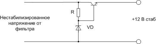
For a powerful transistor, a radiator must be provided. The supply voltage in this case will be less than Ust of the zener diode by 0.6 V. If necessary, the output voltage can be adjusted upwards by turning on a silicon diode (or a chain of diodes). Each element in the chain will increase Vout by about 0.6 V.
Output voltage regulation
If the voltage of the power supply must be regulated from zero, then the optimal circuit would be a parametric stabilizer with the addition of a variable resistor.
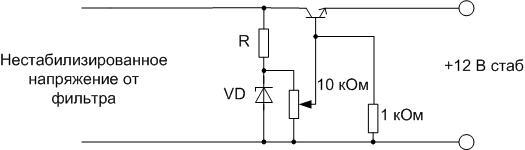
A 1 kΩ resistor connected between the base of the transistor and the common wire will protect the triode from failure if the potentiometer engine circuit breaks.When the knob of the variable resistor is rotated, the voltage at the base of the transistor will change from 0 to Ust of the zener diode with a lag of about 0.6 volts. It should be taken into account that the parameters of the node will be worse due to the use of a potentiometer - the presence of a moving contact (even of good quality) will inevitably reduce the voltage stability at the base of the transistor.
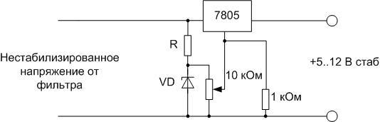
Achieving 0 to 12 volt regulation with the 78XX series integrated regulator is much more difficult. If a regulation range of 5 to 12 V is sufficient, you can use the 7805 chip and turn it on according to the potentiometer circuit. The zener diode should be at a voltage of about 7 volts (KS168 with or without a diode, KS175, etc.). In the lower position of the potentiometer slider, the GND pin is connected to the common wire, and the output will be 5 volts. When the engine is shifted to the upper output, the voltage on it will grow up to Ust of the zener diode and add up with the stabilization voltage of the microcircuit.
You can use the LM317 chip. It also has three terminals and is specifically designed to create regulated sources. But this stabilizer has a lower voltage threshold starting at 1.25 volts. There are many circuits on the Internet on the LM317 with adjustment from zero, but 90+ percent of these circuits are inoperative.
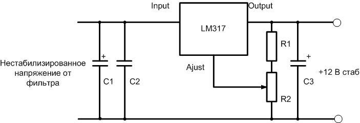
Read also:Homemade power supply with voltage and current regulation 0 to 30V
Instrument layout
After all the nodes are selected, or there is a clear idea of \u200b\u200bwhat they will be, you can proceed to the layout of the device. It is also important to understand what the future case of the device will be like.You can choose ready-made, you can do it yourself if you have materials and skills.
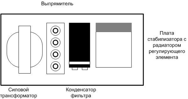
There are no special rules for the layout of nodes inside the case. But it is desirable to arrange the nodes so that they are connected by conductors in series, as in the diagram, and along the shortest distance. The output terminals are best placed on the side opposite the mains cable. It is better to fix the power switch and fuse on the back of the device. For the rational use of the inter-case space, some of the nodes can be installed vertically, but it is better to fix the diode bridge horizontally. When mounted vertically, convection currents of hot air from the lower diodes will flow around the upper elements and additionally heat them.
For those who do not understand, watch the video: A simple do-it-yourself power supply.
Assembling a fixed-power DC power supply is easy. This is within the power of an average master, you only need elementary knowledge in electrical engineering and minimal installation skills.