How to connect LED to Arduino board
The Arduino platform is wildly popular all over the world. An ideal tool for the first steps in the development of programming and hardware management. As you grow in skill, you can scale up the architecture by adding peripherals and build more complex systems that run more complex programs. Arduino Uno and Arduino Nano boards are suitable for initial training. On their example, the connection of the LED to the Arduino is considered.
What is Arduino Uno and Arduino Nano
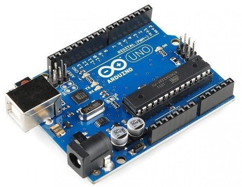
The basis of the Arduino Uno board is the ATmega328 microcontroller. It also has additional elements:
- quartz resonator;
- reset button;
- USB connector;
- integrated voltage stabilizer;
- power connector;
- several LEDs for indicating modes;
- communication chip for USB channel;
- connector for in-circuit programming;
- a few more active and passive elements.
All this allows you to take the first steps without using a soldering iron, and avoid the stage of manufacturing a printed circuit board.The unit is powered by an external voltage source of 7..12 V or via a USB connector. Through it, the module is connected to the PC to download the sketch. The board has a 3.3 V voltage source for powering external devices. 6, 14 general-purpose digital outputs are available for operation. The load capacity of the digital output when powered by 5 V is 40 mA. This means that an LED can be directly connected to it via limiting resistor.
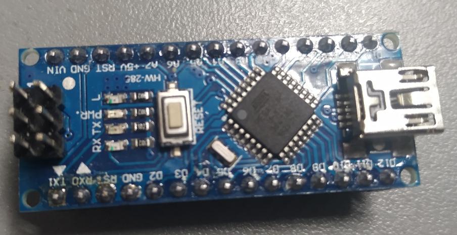
The Arduino Nano board is fully compatible with the Uno, but is smaller and has some differences and simplifications, as shown in the table.
| Pay | Controller | Connector for external power supply | Microchip for USB communication | USB connector |
|---|---|---|---|---|
| Arduino Uno | ATmega328 | There is | ATmega8U2 | USB A-B |
| Arduino Nano | ATmega328 | Not | FT232RL | micro USB |
The differences are not fundamental and do not matter for the topic of the review.
What you need to connect LED to Arduino board
There are two options for connecting the LED. For learning purposes, you can choose any.
- Use built-in LED. In this case, nothing else is needed, except for a cable for connecting to a PC via a USB connector - for power and programming. It makes no sense to use an external voltage source to power the board: the current consumption is low.
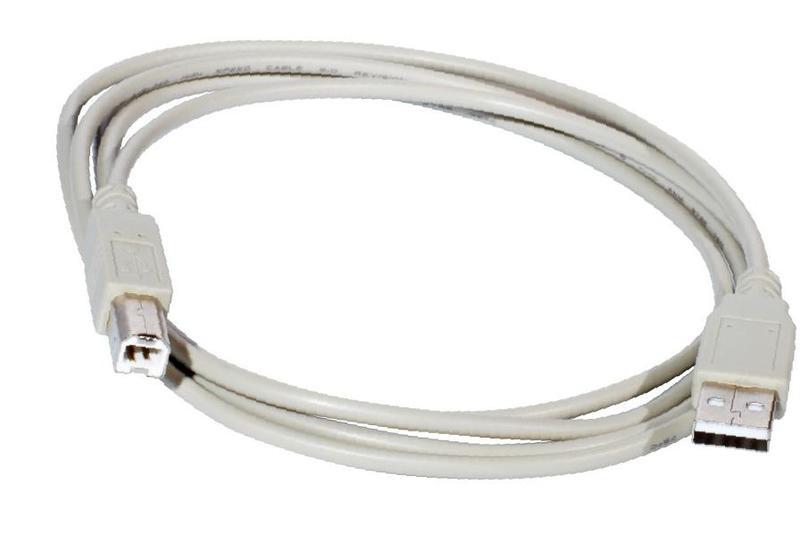
![USB A-B cable]() USB A-B cable to connect Arduino Uno to PC.
USB A-B cable to connect Arduino Uno to PC. - Connect external LEDs. Here you will additionally need:
- the LED itself;
- current-limiting resistor with a power of 0.25 W (or more) with a nominal value of 250-1000 ohms (depending on the LED);
- wires and a soldering iron for connecting an external circuit.
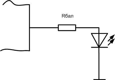
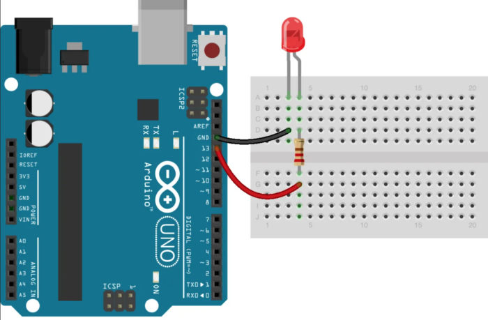
LEDs are connected cathode to any digital output of the microcontroller, anode to a common wire through a ballast resistor. With a large number of LEDs, an additional power source may be needed.
Is it possible to connect multiple LEDs to one output
It may be necessary to connect an external LED or group of LEDs to any of the outputs. The load capacity of one output of the microcontroller, as mentioned, is small. One or two LEDs with a current consumption of 15 mA can be directly connected to it in parallel. It is not worth testing the survivability of the output with a load on the verge of possibility or exceeding it. It is better to use a switch on a transistor (field or bipolar).

Resistor R1 must be chosen so that the current through it does not exceed the load capacity of the output. It is better to take half or less of the maximum. So, to set a moderate current in 10 mA, the resistance at 5 volts of supply should be 500 ohm.
Each LED must have its own ballast resistor, it is undesirable to replace it with one common one. Rbal is chosen so as to set its operating current through each LED. So, for a supply voltage of 5 volts and a current of 20 mA, the resistance should be 250 ohms or the nearest standard value.
It is necessary to ensure that the total current through the collector of the transistor does not exceed its maximum value. So, for the KT3102 transistor, the largest Ik should be limited to 100 mA. This means that no more than 6 LEDs with current can be connected to it. 15 mA. If this is not enough, a more powerful key must be used.This is the only restriction for choosing an n-p-n transistor in such a circuit. Here, theoretically, it is also necessary to take into account the gain of the triode, but for these conditions (input current 10 mA, output 100) it should be only at least 10. Any modern transistor can produce such h21e.
Such a circuit is suitable not only for boosting the current output of the microcontroller. So you can connect sufficiently powerful actuators (relays, solenoids, electric motors) powered by increased voltage (for example, 12 volts). When calculating, you need to take the corresponding voltage value.
You can also use to execute keys MOSFETs, but they may require a higher voltage to open than the Arduino can output. In this case, additional circuits and elements must be provided. To avoid this, it is necessary to use the so-called "digital" field-effect transistors - they need 5 volt to open. But they are less common.
Programmatically Controlling an LED
Simply connecting an LED to the output of the microcontroller does little. It is necessary to master the control of the LED from the Arduino programmatically. This can be done in the Arduino language, which is based on C (C). This programming language is an adaptation of C for initial learning. After mastering it, the transition to C ++ will be easy. To write sketches (as programs for Arduino are called) and debug them live, you need to do the following:
- install the Arduino IDE on a personal computer;
- you may need to install a driver for the USB communication chip;
- connect the board to a PC using a USB-microUSB cable.
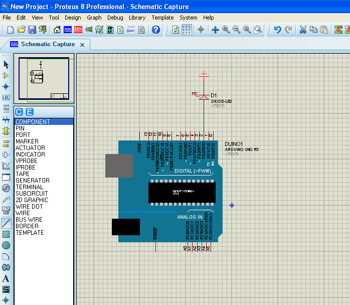
Computer simulators can be used to debug simple programs and circuits. Simulation of the operation of Arduino Uno and Nano boards is supported, for example, by Proteus (starting from version 8). The convenience of the simulator is that it is impossible to disable the hardware with an erroneously assembled circuit.
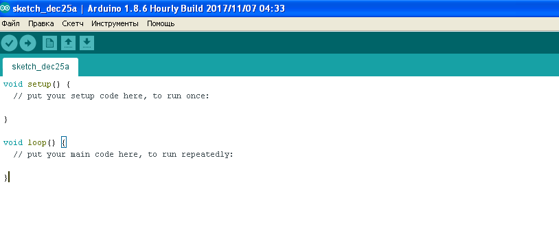
Sketches consist of two modules:
- setup - is executed once when the program is started, initializes the variables and modes of operation of the iron;
- loop – is executed cyclically after the setup block to infinity.
For LED connection you can use any of the 14 free pins (pins), which are often incorrectly called ports. In fact, the port is, simply speaking, a group of pins. Pin is just an element.
An example of control is considered for pin 13 - an LED is already connected to it on the board (through an amplifier-follower on the Uno board, through a resistor on the Nano). To work with a port pin, it must be configured in input or output modes. It is convenient to do this in the setup body, but not necessary - the output destination can be changed dynamically. That is, during the execution of the program, the port can work either for input or for data output.
The initialization of pin 13 of the Arduino (pin PB5 of port B of the ATmega 328 microcontroller) is as follows:
void setup()
{
pinMode(13, Output);
}
After executing this command, pin 13 of the board will work in output mode, by default it will be logic low. During the execution of the program, zero or one can be written to it. The unit record looks like this:
void loop()
{
digitalWrite(13, HIGH);
}
Now, pin 13 of the board will be set high - a logical one, and it can be used to light the LED.
To turn off the LED, you need to set the output to zero:
digitalWrite(13, LOW);
So, by writing alternately one and zero to the corresponding bit of the port register, you can control external devices.
Now you can complicate the Arduino program to control the LED and learn how to blink the light emitting element:
void setup()
{
pinMode(13, Output);
}
void loop()
{
digitalWrite(13, HIGH);
delay(1000);
digitalWrite(13, LOW);
delay(1000);
}
Team delay(1000) creates a delay of 1000 milliseconds, or one second. By changing this value, you can change the frequency or duty cycle of the LED blinking. If an external LED is connected to another output of the board, then in the program, instead of 13, you must specify the number of the selected pin.
For clarity, we recommend a series of videos.
Having mastered the LED connections to the Arduino and learned how to control it, you can move to a new level and write other, more complex programs. For example, you can learn how to switch two or more LEDs with a button, change the blinking frequency using an external potentiometer, adjust the brightness of the glow using PWM, change the color of an RGB emitter. The level of tasks is limited only by the imagination.