How to calculate LED resistor - formulas with examples + online calculator
LEDs of different shades of color have different direct operating voltages. They are set by choosing the current-limiting resistance of the LED. To bring the lighting device to the nominal mode, you need to power the p-n junction with a working current. To do this, calculate the resistor for the LED.
LED voltage table depending on color
The operating voltages of the LEDs are different. They depend on the materials of the semiconductor p-n junction and are related to the wavelength of light emission, i.e. glow color shade.
The table of nominal modes of different shades of color for calculating the damping resistance is given below.
| Glow color | Forward voltage, V |
|---|---|
| Shades of white | 3–3,7 |
| Red | 1,6-2,03 |
| Orange | 2,03-2,1 |
| Yellow | 2,1-2,2 |
| Green | 2,2-3,5 |
| Blue | 2,5-3,7 |
| Violet | 2,8-4,04 |
| Infrared | No more than 1.9 |
| UV | 3,1-4,4 |
It can be seen from the table that 3 volts can turn on emitters of all types of glow, except for devices with a white tint, partially violet and all ultraviolet. This is due to the fact that you need to “spend” some part of the power supply voltage on limiting the current through the crystal.
With power supplies of 5, 9 or 12 V, you can power single diodes or their series chains of 3 and 5-6 pieces.
Serial chains reduce the reliability of the devices in which they are used by about a factor corresponding to the number of LEDs. And parallel connection increases reliability in the same proportion: 2 chains - 2 times, 3 - 3 times, etc.
But the duration of their operation, unprecedented for light sources, from 30-50 to 130-150 thousand hours, justifies the drop in reliability, because. the service life of the device depends on it. Even 30-50 thousand hours of work for 5 hours a day - 4 hours in the evening and 1 in the morning every day is 16-27 years of work. During this time, most of the lamps will become obsolete and will be disposed of. Therefore, serial connection is widely used by all manufacturers of LED devices.
Online calculator for calculating LEDs
For automatic calculation, you will need the following data:
- source or power supply voltage, V;
- rated forward voltage of the device, V;
- direct rated operating current, mA;
- the number of LEDs in a chain or connected in parallel;
- LED wiring diagram(s).
The initial data can be taken from the passport of the diode.
After entering them into the corresponding windows of the calculator, click on the "Calculate" button and get the nominal value of the resistor and its power.
Calculation of the value of the resistor-current limiter
In practice, two types of calculation are used - graphical, according to the current-voltage characteristic of a particular diode, and mathematical - according to its passport data.
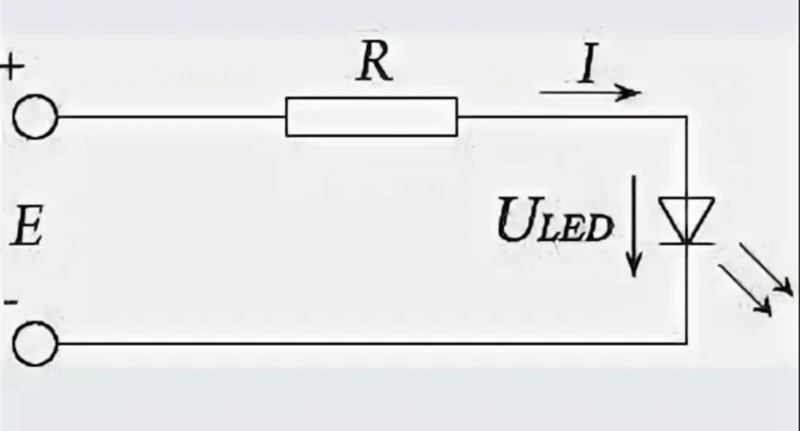
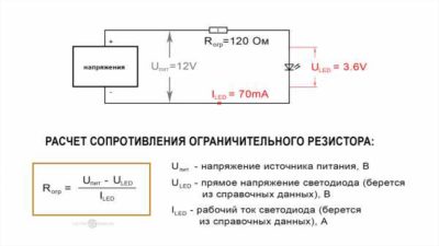
On the image:
- E - a power source with a value of E at the output;
- "+" / "-" - the polarity of the LED connection: "+" - anode, shown as a triangle on the diagrams, "-" - cathode, on the diagrams - a transverse dash;
- R – current-limiting resistance;
- Uled - direct, it is also the operating voltage;
- I - operating current through the device;
- the voltage across the resistor is denoted as UR.
Then the calculation scheme will take the form:
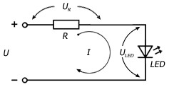
Calculate the resistance to limit the current. Voltage U distributed in the chain like this:
U = UR + Uled or UR + I×Rled, in volts,
where Rled- internal differential resistance of the p-n junction.
By mathematical transformations, we obtain the formula:
R = (U-Uled)/I, in Ohm.
the value Uled can be selected from passport values.
Let's calculate the value of the current-limiting resistor for the Cree LED model Cree XM–L, which has a T6 bin.
His passport data: typical nominal ULED = 2.9 V maximum ULED = 3.5 V, operating current ILED\u003d 0.7 A.
For calculation we use ULED = 2.9 V.
R = (U-Uled) / I \u003d (5-2.9) / 0.7 \u003d 3 Ohms.
The calculated value is 3 ohms. We select an element with an accuracy tolerance of ± 5%. This accuracy is more than enough to set the operating point at 700 mA.
Round up the resistance value. This will reduce the current, the luminous flux of the diode and increase the reliability of operation with a more gentle thermal regime of the crystal.
Calculate the required power dissipation for this resistor:
P = I² × R = 0.7² × 3 = 1.47 W
For reliability, we round it up to the nearest larger value - 2 watts.
Series and Parallel Schemes LEDs are widely used and show the features of these types of connection. Connecting identical elements in series divides the source voltage equally between them. With different internal resistances - in proportion to the resistances. When connected in parallel, the voltage is the same, and the current is inversely proportional to the internal resistances of the elements.
When connected in series LED
When connected in series, the first diode in the chain is connected by the anode to the “+” of the power source, and by the cathode to the anode of the second diode. And so on until the last in the chain, the cathode of which is connected to the "-" source. The current in a series circuit is the same in all its elements. Those. through any light device it is of the same magnitude. The internal resistance of the open, i.e. emitting light crystal, is tens or hundreds of ohms. If 15-20 mA flows through the circuit at a resistance of 100 ohms, then each element will have 1.5-2 V. The sum of the voltages on all devices should be less than that of the power source. The difference is usually quenched with a special resistor that performs two functions:
- limits the rated operating current;
- provides the rated forward voltage to the LED.
When connected in parallel
Parallel connection can be done in two ways.
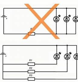
The top picture shows how to enable it is not desirable. With this connection, one resistance will ensure the equality of currents only with ideal crystals and the same length of the lead wires. But the variation in the parameters of semiconductor devices during manufacture does not make it possible to make them the same. And the selection of the same - dramatically increases the price. The difference can reach 50-70% or more. Having assembled the structure, you will get a difference in the glow of at least 50-70%. In addition, the failure of one emitter will change the operation of all: if the circuit is broken, one will go out, the rest will shine brighter by 33% and will start to heat up more. Overheating will contribute to their degradation - a change in the shade of the glow and a decrease in brightness.
In the event of a short circuit as a result of overheating and combustion of the crystal, the current-limiting resistance may fail.
The lower option allows you to set the desired operating point of any diode, even with their different rated power.
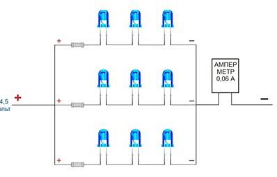
For a voltage of 4.5 V, three LED elements and one current-limiting resistance are connected in series. The resulting chains are connected in parallel. 20 mA flows through each diode, and 60 mA flows through all together. On each of them it turns out less than 1.5 V, and on the current limiter - no less than 0.2-0.5 V. Interestingly, if you use a 4.5 V power supply, then only infrared diodes can work with it with a forward voltage of less than 1.5 V, or you need to increase the supply to at least 5 V.
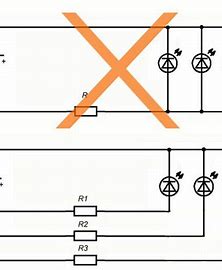
Directly parallel connection of LED elements (upper part of the circuit) is not recommended because of the parameter spread of 30-50% or more.Use a circuit with individual resistances for each diode (lower part) and already connect pairs of diode-resistor in parallel.
When one LED
Resistor for single LED it is used only at their powers up to 50-100 mW. At high power values, the efficiency of the power circuit decreases markedly.
If the forward working voltage of the diode is significantly less than the power supply voltage, the use of a limiting resistor leads to large losses. Power of high quality and stability, with carefully filtered ripples, provided by 3-5 types of protection of the power supply is not converted into light, but simply passively dissipated in the form of heat.
At high powers they go drivers – current stabilizers of nominal value.
Using a current-limiting resistor to set the operating LED characteristics is a simple and reliable way to ensure its optimal operation.
Video examples of the simplest calculation of resistance.
But with a diode power of more than a hundred milliwatts, it is necessary to use autonomous or built-in sources of current stabilization or drivers.