Connecting the LED to 220V
LEDs are widely used as light sources. But they are designed for low supply voltage, and often it becomes necessary to turn on the LED in a 220 volt household network. With little knowledge of electrical engineering and the ability to perform simple calculations, this is possible.
Connection methods
The standard operating conditions for most LEDs are 1.5-3.5 V voltage and 10-30 mA current. When the device is connected directly to the household electrical network, its lifetime will be tenths of a second. All the problems of connecting LEDs to a network of increased voltage compared to the standard operating voltage come down to repaying the excess voltage and limiting the current flowing through the light emitting element. Drivers - electronic circuits - cope with this task, but they are quite complex and consist of a large number of components.Their use makes sense when powering an LED matrix with many LEDs. There are simpler ways to connect one element.
Connecting with a resistor
The most obvious way is to connect a resistor in series with the LED. It will drop excess voltage, and it will limit the current.
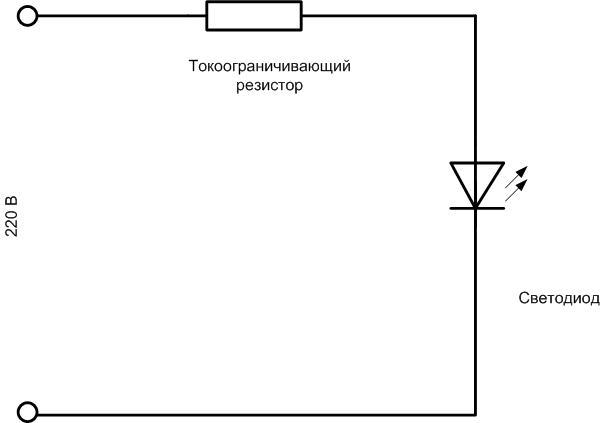
The calculation of this resistor is carried out in the following sequence:
- Let there be an LED with a rated current of 20 mA and a voltage drop of 3 V (see the manual for the actual parameters). It is better to take 80% of the nominal for the operating current - LED in light conditions will live longer. Iwork=0.8 Inom=16 mA.
- On the additional resistance, the mains voltage will drop minus the voltage drop across the LED. Urab \u003d 310-3 \u003d 307 V. Obviously, almost all the voltage will be on the resistor.
Important! When calculating, it is necessary to use not the current value of the mains voltage (220 V), but the amplitude (peak) value - 310 V.
- The value of the additional resistance is found according to Ohm's law: R = Urab / Irab. Since the current is selected in milliamps, the resistance will be in kiloohms: R \u003d 307/16 \u003d 19.1875. The closest value from the standard range is 20 kOhm.
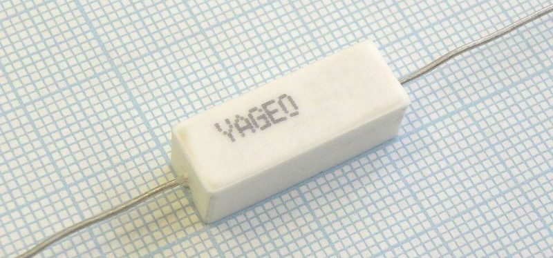
- To find the power of the resistor using the formula P=UI, the operating current must be multiplied by the voltage drop across the quenching resistance. With a rating of 20 kOhm, the average current will be 220 V / 20 kOhm = 11 mA (here you can take into account the effective voltage!), And the power will be 220V * 11mA = 2420 mW or 2.42 W. From the standard range, you can choose a 3 W resistor.
Important! This calculation is simplified, it does not always take into account the voltage drop across the LED and its on-state resistance, but for practical purposes the accuracy is sufficient.
So you can connect a chain of series-connected LEDs. When calculating, it is necessary to multiply the voltage drop on one element by their total number.
Series connection of high reverse voltage diode (400 V or more)
The described method has a significant drawback. Light-emitting diode, like any device based on a p-n junction, it passes current (and glows) with a direct half-wave of alternating current. With a reverse half-wave, it is locked. Its resistance is high, much higher than the ballast resistance. And the mains voltage with an amplitude of 310 V applied to the chain will drop mostly on the LED. And it is not designed to work as a high-voltage rectifier, and can fail pretty soon. To combat this phenomenon, it is often recommended to include in series an additional diode that can withstand reverse voltage.
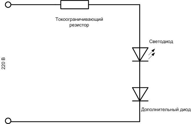
In fact, with this turn on, the applied reverse voltage will be divided approximately in half between the diodes, and the LED will be slightly lighter when about 150 V or a little less falls on it, but its fate will still be sad.
Shunting an LED with a conventional diode
The following scheme is much more efficient:
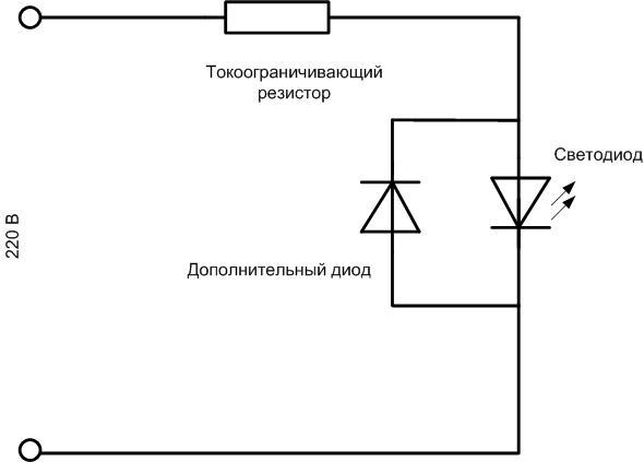
Here, the light emitting element is connected opposite and parallel to the additional diode. With a negative half-wave, the additional diode will open, and all the voltage will be applied to the resistor. If the calculation made earlier was correct, then the resistance will not overheat.
Back-to-back connection of two LEDs
When studying the previous circuit, the thought cannot but come - why use a useless diode when it can be replaced with the same light emitter? This is correct reasoning. And logically the scheme is reborn in the following version:
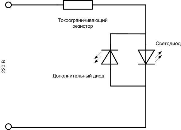
Here, the same LED is used as a protective element. It protects the first element during the reverse half-wave and radiates at the same time. With a direct half-wave of a sinusoid, the LEDs change roles. The advantage of the circuit is the full use of the power supply. Instead of single elements, you can turn on chains of LEDs in forward and reverse directions. The same principle can be used for the calculation, but the voltage drop across the LEDs is multiplied by the number of LEDs installed in one direction.
With a capacitor
A capacitor can be used instead of a resistor. In an AC circuit, it behaves somewhat like a resistor. Its resistance depends on the frequency, but in a household network this parameter is unchanged. For calculation, you can take the formula X \u003d 1 / (2 * 3.14 * f * C), where:
- X is the reactance of the capacitor;
- f is the frequency in hertz, in the case under consideration it is equal to 50;
- C - capacitance of the capacitor in farads, to convert to uF use a factor of 10-6.
In practice, the following formula is used:
C \u003d 4.45 * Iwork / (U-Ud), where:
- C is the required capacitance in microfarads;
- Irab - operating current of the LED;
- U-Ud - the difference between the supply voltage and the voltage drop across the light-emitting element - is of practical importance when using a chain of LEDs. When using a single LED, it is possible to take the U value equal to 310 V with sufficient accuracy.
Capacitors can be used with an operating voltage of at least 400 V.The calculated values for currents characteristic of such circuits are given in the table:
| Operating current, mA | 10 | 15 | 20 | 25 |
| Ballast capacitor capacity, uF | 0,144 | 0,215 | 0,287 | 0,359 |
The resulting values are quite far from the standard range of capacities. So, for a current of 20 mA, the deviation from the nominal value of 0.25 μF will be 13%, and from 0.33 μF - 14%. resistor can be selected much more accurate. This is the first drawback of the scheme. The second one has already been mentioned - capacitors of 400 V and above are quite large. And that is not all. When using a ballast tank, the circuit is overgrown with additional elements:
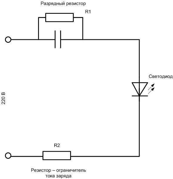
The resistance R1 is set for safety purposes. If the circuit is powered from 220 V, and then disconnected from the network, then the capacitor will not discharge - without this resistor, the discharge current circuit will be absent. If you accidentally touch the terminals of the container, it is easy to get an electric shock. The resistance of this resistor can be selected in several hundred kilo-ohms, in working condition it is shunted by a capacitance and does not affect the operation of the circuit.
Resistor R2 is needed to limit the inrush of the charging current of the capacitor. Until the capacitance is charged, it will not serve as a current limiter, and during this time the LED may have time to fail. Here you need to choose a value of several tens of ohms, it will also not have an effect on the operation of the circuit, although it can be taken into account in the calculation.
An example of turning on an LED in a light switch
One of the common examples of the practical use of an LED in a 220 V circuit is to indicate the off state of a household switch and make it easier to find its location in the dark. The LED here operates at a current of about 1 mA - the glow will be dim, but noticeable in the dark.
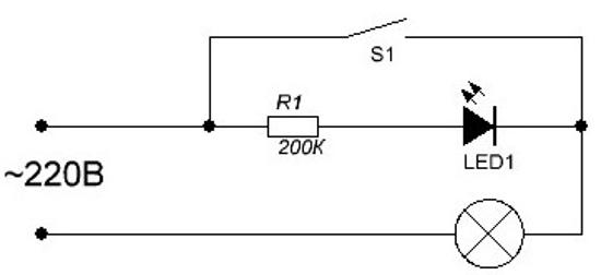
Here the lamp serves as an additional current limiter when the switch is in the open position, and will take on a small fraction of the reverse voltage. But the main part of the reverse voltage is applied to the resistor, so the LED is relatively protected here.
Video: WHY NOT TO INSTALL A LIGHTED SWITCH
Safety
Safety precautions when working in existing installations are regulated by the Rules for labor protection during the operation of electrical installations. They do not apply to a home workshop, but their basic principles must be taken into account when connecting an LED to a 220 V network. The main safety rule when working with any electrical installation is that all work must be carried out with the voltage removed, eliminating erroneous or involuntary, unauthorized switching on. After switching off the switch, the absence of voltage must be check with a tester. Everything else is the use of dielectric gloves, mats, the imposition of temporary grounding, etc. difficult to do at home, but we must remember that there are few security measures.