How to connect light through a switch - wiring diagrams
The household light switch has long become a familiar appliance in household use and in production. In addition to its direct function of closing and opening the electrical circuit, it often carries a decorative and service load. To get the greatest comfort using the capabilities of modern devices, you need to understand their varieties and applications.
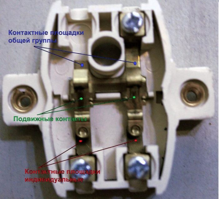
What is a switch
A switch is a household appliance whose purpose is to supply voltage to lighting lamps and turn it off.An ordinary consumer does not think about its internal structure, although it is quite simple. Each key controls a moving contact, which, together with a fixed contact, closes or opens an electrical circuit. Plus terminals to which electrical wires are attached, plus decorative details. This is the household electrical switch.
It is usually installed on the wall. The installation site is regulated by the Rules for the installation of electrical installations. It is forbidden to mount control devices closer than 50 cm from gas pipes, as well as in damp rooms (bathrooms, showers, etc.). In children's institutions, switches are placed at a height of at least 180 cm. Otherwise, the Rules only recommend installing switching devices at the entrance to the room from the side of the door handle at a height of 1 meter.
Varieties of electrical appliances
Despite the fact that the task of any switch is to close and open an electrical circuit by controlling lamps, there are many varieties of household switching devices. They can be classified according to different criteria depending on the application.
Performance classification
Switching devices according to the type of installation are divided into:
- invoices;
- internal.
The first type of switches is mounted on a lining panel, usually used for open wiring (but can also be used in conjunction with a hidden one). Its main advantage is ease of installation. The disadvantages include a higher probability of mechanical damage, and such devices look less aesthetically pleasing.Internal switching devices are more recessed into the wall (it is more difficult to damage, for example, when rearranging furniture), they look more beautiful. But they require the arrangement of socket boxes and are used in conjunction with hidden wiring.
By degree of protection
The degree of protection determines where the switch can be installed, how protected it is from outside penetration. The level of protection is marked with the letters IP and two digits, the first of which indicates the protection of the case from the penetration of solid particles, the second - from the ingress of moisture.
| Meaning | The first digit is the level of protection against ingress of solid particles. | The second digit is the level of protection against water penetration. |
| x | not defined | |
| 0 | No protection | |
| 1 | The shell does not pass particles of 50 mm or more | Protected against vertically falling drops |
| 2 | The shell does not allow particles of 12.5 mm or more to pass through | Protected against drops falling at an angle of 15 degrees |
| 3 | The shell does not allow particles of 2.5 mm or more to pass through | Protected against drops falling at an angle of 60 degrees |
| 4 | The shell does not pass particles of 1 mm or more | Protected from any drops |
| 5 | The shell does not let dust through | Protected against water jets |
| 6 | Complete dust protection | Protected from strong jets |
| 7 | --- | Allowed to be briefly immersed to a depth of 1 m |
| 8 | --- | Allowed to be immersed to a depth of up to 1 m for up to 10 minutes |
So, devices with IP21 can only be installed indoors. On the street or in the attic, switches with IP44 or IP54 are suitable.
By terminal type
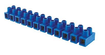
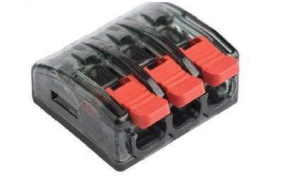
Two types of terminals are used to connect wires:
- screw;
- clamping (spring).
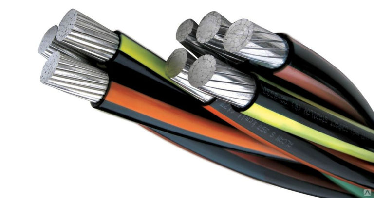
The former are considered more reliable in operation. The second is more convenient when connecting. If aluminum wiring is used, then due to the ductility of aluminum, the screw terminals must be periodically tightened. The springs compress themselves.
By number of keys
The following switches are available for sale:
- single-key - used to control a single load, consisting of one or more parallel lamps;
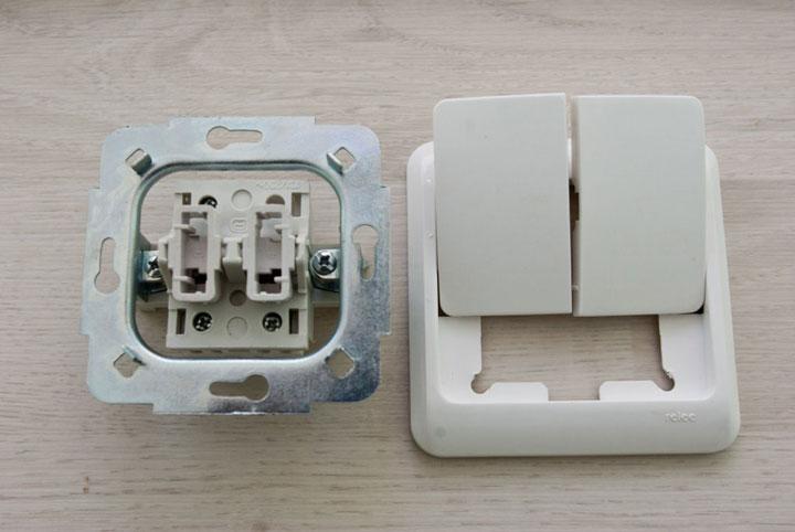
- two-key - to control two separate loads or a chandelier with two groups of lamps;
- three-key - control three separate loads or a chandelier with three groups of lamps.
There are no technical restrictions on the creation of switches with a large number of control channels, but from an aesthetic point of view, three buttons are perhaps the maximum.
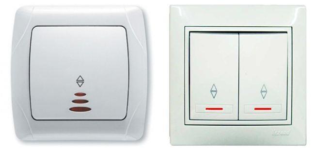
Availability of light indication
There are devices equipped with a backlight chain. It has several functions:
- highlighting the location of the switch (useful when entering a dark room);
- indication of the inclusion of the contact group;
- in some cases, an indication of a lamp failure.
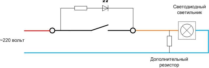
Usually the backlight circuit is made on LEDs or on small neon bulbs. The switch circuit with one or two keys and an LED is performed according to the same principle.
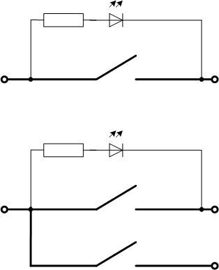
The current that initiates the glow of the LED flows through limiting resistor, the light emitting element itself and the lamp. When the main contact is closed, the lighting circuit is shunted and the LED goes out. If an incandescent lamp is used as a lamp, and it burns out, the circuit will also be open, and the LED will not light at any position of the device key. In two-button devices, the chain is usually placed parallel to one contact group.
Contact functionality
Most household switching devices can have a contact group of the following versions:
- conventional (closing-opening);
- passthrough (changeover contacts);
- cross (two changeover contact groups connected in a special way).
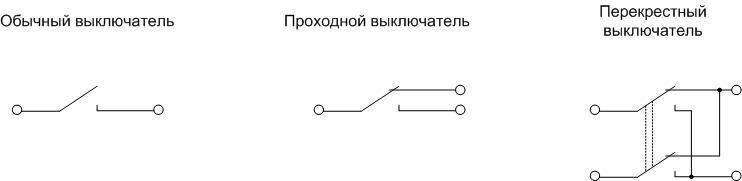
The last two types are, in fact, switches.
Ordinary and pass-through switches are also available in two- and three-gang versions, in which case they have two or three contact groups, respectively. The use of each type of apparatus is described below.
Type of wiring
Cables for connecting the elements of the lighting system in the premises are laid in two ways:
- open;
- hidden.
The second option outright wins in terms of aesthetics, fire safety and almost zero probability of cable damage. But for hidden wiring, cutting channels (strobes) in a brick, concrete wall or plaster is required. Certain restrictions are imposed on the arrangement of strobes:
- channels can only be performed horizontally or vertically (at an angle of 0 or 90 degrees);
- it is impossible to cut horizontal strobes in load-bearing walls.
Other restrictions and rules are contained in SNiP 3.05.06-85 (SP 76.13330.2012).
Strobes will not be needed if hidden wiring is laid inside a drywall partition. Exposed wiring is carried out on rack insulators.
Materials and tools for connecting devices
The minimum required set of tools for mounting switches looks like this:
- wire cutters for shortening cables;
- fitter's knife for removing insulation;
- a set of screwdrivers for installing the devices and tightening the terminal screws.
If you plan to connect the wires in the junction box by twisting followed by soldering, you will also need an electric soldering iron with a set of consumables, as well as insulation material - electrical tape or plastic caps. If the use of terminals is intended, then spring (clamp) or screw terminals will be needed.
If the wiring is being equipped from scratch, then for hidden wiring, strobes must be made. To do this, you need one of the tools (in descending order of the cost of the appliance, speed and quality of work):
- wall chaser;
- Bulgarian;
- perforator;
- chisel with a hammer.
To install socket boxes in a concrete or brick wall, it is necessary to make recesses using a crown. For open wiring, purchase cable ducts or post insulators. To attach them to the wall and ceiling, you will need a drill and dowels.
Device connection diagrams
Depending on the type of device and its application in a particular situation, the connection diagrams of the switches will vary.
Single key switch
The connection diagram of a switch with one button is the simplest. The contacts of the device in one position are collected, and in the other they break the electrical circuit.
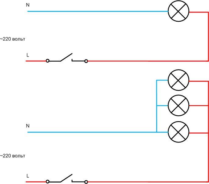
The lamp can be one, or maybe several, if you turn them on parallel. They will be controlled synchronously. The main thing is not to exceed the load capacity of the contacts of the device.
Important! For simplicity, the diagram does not show the protective earth conductor PE - it does not affect the performance of the lighting system, but it directly affects safety. It goes from the switchboard to the lamp and is connected to the corresponding terminal.
Two- and three-button devices
Switches with two and three contact groups independently switch two or three loads. Such loads can be:
- lamps located in different rooms or zones;
- different lighting systems of one room (main and spot);
- different groups of lamps in a multi-arm chandelier.
Fundamentally, the schemes do not differ (except for the number of keys), but the topology of the cable products and the wiring in the junction box will differ.
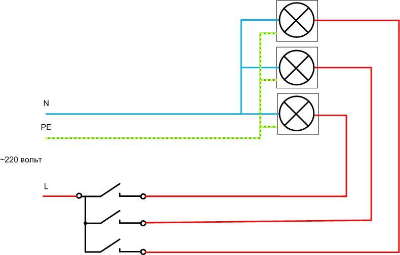
For example, a diagram of switching on a device with three buttons for controlling three separate lamps is shown.
Application of the switch through the lamp with a fan
Ceiling lights combined with a fan are available for sale. There are two options for managing such devices:
- using a one-button switch;
- using a two-button device.
The first option is simpler and requires less consumption of cable products.
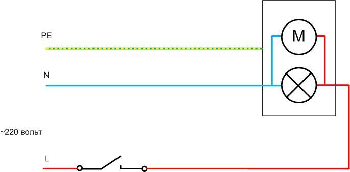
But in this case, the fan and the lamp are controlled at the same time. It is not possible to turn on the airflow or lighting separately.
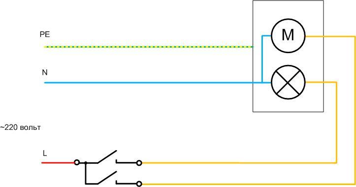
The second scheme is more complicated, it will require cables with a large number of cores. But the fan and lighting are switched separately.
Motion sensor for lighting control
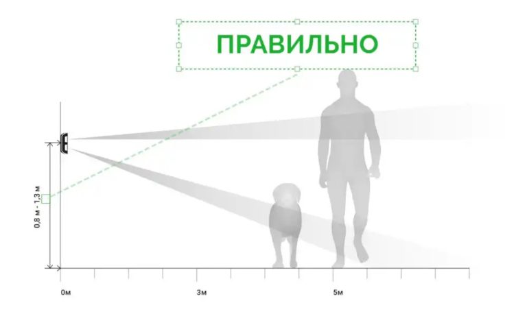
To turn on the lighting only at those moments when there is a moving object (a person or a car) in the controlled room or on the territory, apply motion sensors. Their use provides significant energy savings, and the connection scheme has certain features.
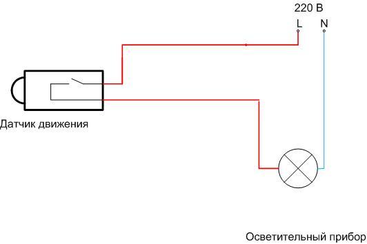
The simplest case is when a motion sensor of a two-wire design is used. In this case, its connection does not differ from a conventional switch - it is included in the break of the phase wire.
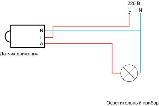
But many motion sensors need a three-wire connection to power their own circuitry, which in most cases will require a reconstruction of the lighting system.
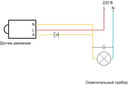
Therefore, in some cases, a modified circuit can be applied - a diode and a capacitor are added to it. As a result, a three-wire detector can be included in the phase wire break. But such a scheme is not always applicable, it depends on the type of lamp.
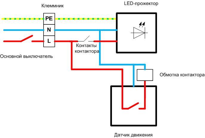
It should also be borne in mind that not always the contacts of the motion sensor can directly switch the load. In this case, it is necessary to connect a low-power switch to the load through an intermediate repeater relay.
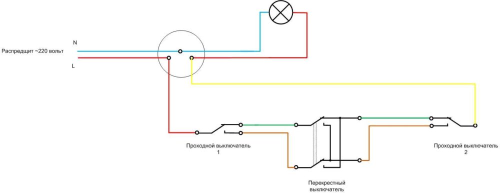
Using a walk-through switch
Having two checkpoints device, it is possible to perform such a lighting scheme in which the light can be turned on and off from two points. Such a control system is convenient in long walk-through corridors, large warehouses, in bedrooms (at the entrance the light turns off, when you go to bed you can turn it off - and vice versa in the morning).
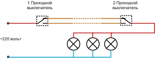
When manipulating one apparatus, it does not matter in what position the second one is.It can be seen from the diagram that you can break and reassemble the circuit with any switch with a changeover group of contacts.
Application of cross electrical appliance
In T-shaped corridors, in double bedrooms, in children's rooms, it may be necessary to turn lights on and off independently from three independent places. Such a circuit cannot be assembled on pass-through devices alone; a cross (reversing) switch will be required.
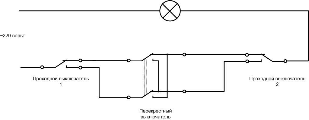
It is obvious from the diagram that any switch collects or opens the circuit in one of its positions, regardless of other devices.
Connecting a backlit device
In the era of incandescent lamps, the backlight circuit could be ignored. In the off state, a small through current did not affect the operation of the lighting system. Everything has changed with the advent of energy-saving and LED lamps. In some cases, even a few milliamps of current is enough to cause an unpleasant flashing of the lamp. There are two ways to deal with this phenomenon:
- shunt the lamp with a resistor or capacitor (it is convenient to put the shunt directly on the lamp socket or chandelier connector);
- if the switch switches a group of lamps, you can try replacing one lamp in the group with an incandescent bulb.
In extreme cases, the backlight circuit can be removed.
Video: We connect the backlight on a single-gang switch.
Connection diagram in the junction box
The procedure for connecting conductors in the junction box depends on the general scheme of the lighting system, but general principles can be distinguished:
- a cable is inserted into the box from the switchboard containing phase L, zero working N and (not always) protective PE conductors;
- zero and protective (if any) conductors from the box in transit go to the loads;
- the phase conductor has a break and branches into as many branches as the loads are powered;
- the cable to each luminaire contains a phase conductor, as well as N and PE;
- a switching device is connected to a phase break, a cable with a number of cores equal to the number of switched loads plus a supply phase core is lowered to it.
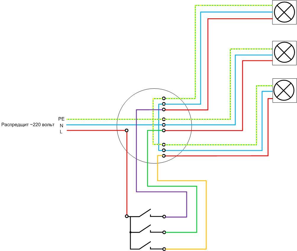
As an example, a rather complicated option is given - switch with three buttons controls three lights:
- the box includes a cable with three cores (including PE);
- a cable with 4 cores (3 + supply) is connected to the three-gang switch;
- each load has its own three-core cable (if there is no protective conductor, a two-core cable);
- N and PE conductors are connected and branched in the box.
In the case of using walk-through and cross switches to control lamps from several places, most of the circuit is assembled by a loop.
Also in this case, it is possible to lay wiring products without using a junction box.
Video lesson: 5 mistakes when disconnecting junction boxes.
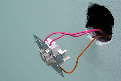
General installation approaches
The general procedure for mounting the switch will be as follows:
- equip the installation site of the device (for a consignment note, install an overlay, for a built-in one, make a recess in the wall and mount a socket box);
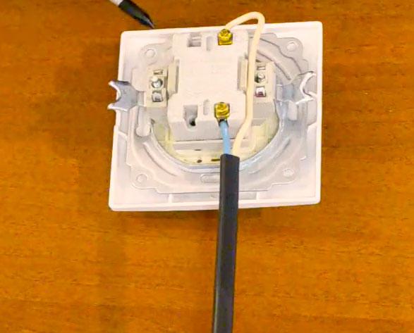
- cut the cable (shorten, remove the upper sheath, strip the cores);
- connect the mounted light switch to the conductors according to the selected scheme (the color marking of the cores will be of great help in this);
- disconnect the conductors in the switch box;
- install the switch in place and fix it (with self-tapping screws, opening the petals);
- reinstall the decorative plastic pieces.
The main principle of installation is maximum safety of work. To do this, the connection of any electrical switch must be carried out with the voltage removed. In this case, everything will go well and the switch will serve for a long time..