How to install a light switch with one key - wiring diagrams
The single-button light switch is the most common household switching device. It performs a simple function - it closes and opens the power circuit of the lighting bulb. Having dealt with its device and the basic principles of fastening, connecting a single switch is easy to do on your own.
Types of single-key switches
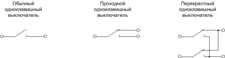
To an inexperienced eye, the answer to this question is simple - a single-key switch contains one key that controls the on-off lighting. With a little deepening into the topic, it turns out that there are several types of electrical appliances with one movable structural element. The three most common are:
- conventional device;
- checkpoint;
- cross.
They differ in the structure of the contact group. Pass-through and cross devices are designed for use in complex systems - for independent lighting control with different points. Outwardly, from the front side, it is almost impossible to distinguish them; marking is not always applied.From the rear, they can be differentiated by the number of pins and by the switching scheme, which is often applied to the reverse side. Therefore, when buying, you need to be careful.
.
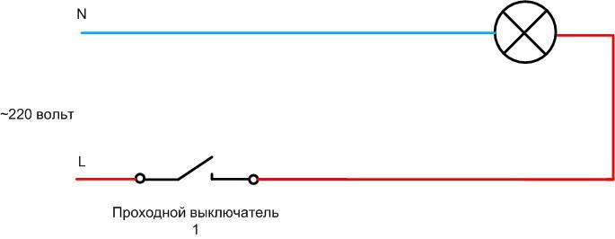
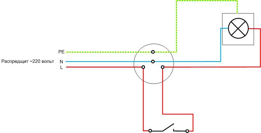
When studying the principle of operation of the pass-through and cross devices, it becomes clear that for the usual switching of lamps (on-off), you can also connect them if they are accidentally purchased or others are not at hand. But these devices are more expensive. And the standard connection diagram of a conventional single-gang switch is shown in the figure.
There are two types of single-key devices:
- overhead;
- interior.
Functionally, they are the same, but the first is mounted on the surface, and the second - in a specially equipped recess.
Switch device with one key
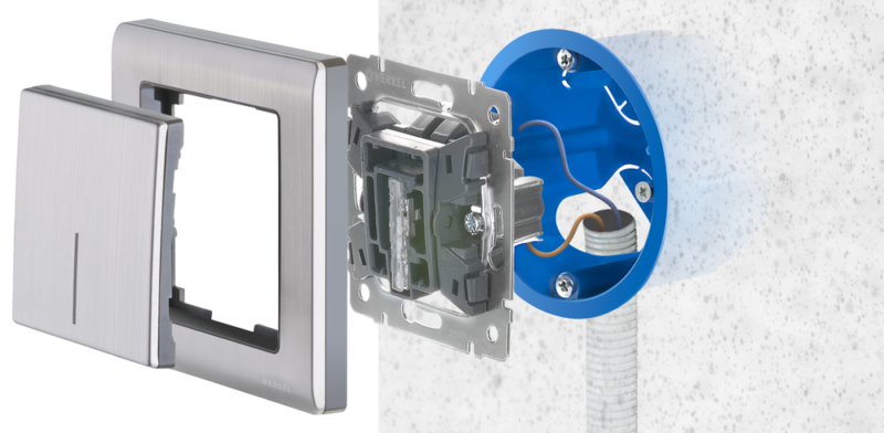
From the outside, a single-key device is seen as a moving part and a decorative frame. Both parts are easy to remove.
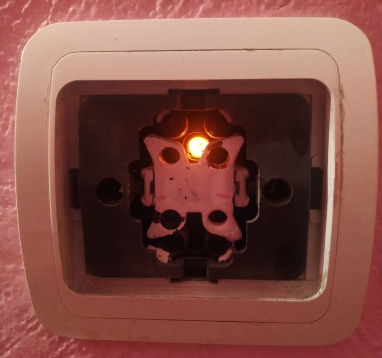
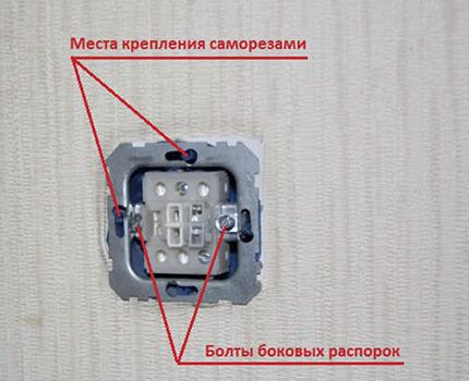
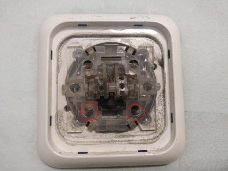
After removing the key, you can see the movable panel associated with the contact group, the terminal screws and the screws of the expansion lugs. If you remove the frame, the screws that secure the device to the wall become visible. You can also see the power indicator, if installed.
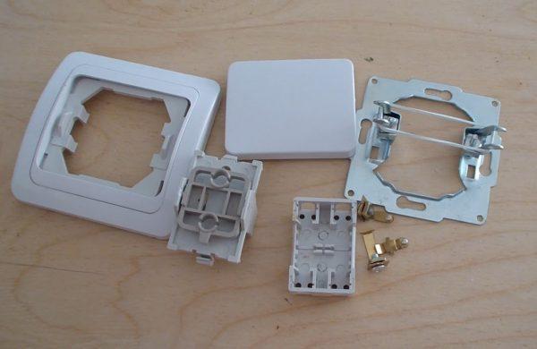
With further disassembly, you can get to the contact group, consisting of movable and fixed contacts. Sometimes the terminal screws are on the back. If they are located on the front, then there is nothing interesting on the back.
Further, single-key switches will also mean other switching devices with one contact group for closing and opening: a rotary design or with a button.
Preparatory work and site selection
Installation of a single-key switch begins with the choice of the location of the switching device itself, the junction box and the lamp. You need to follow the diagram above.
In practice, it is implemented like this:
- the cable from the machine in the switchboard with L, N, PE cores (there may be no protective conductor in the TN-C system) goes to the switch box;
- the same cable goes to the lamp;
- a two-core cable is included in the break of the phase wire to connect the switch.
Important! There is an opinion that to connect the switch, it is also necessary to lay a cable of three cores. One conductor will not be used, but it may come in handy when upgrading the system in the future (installing a through passage or reversing device).
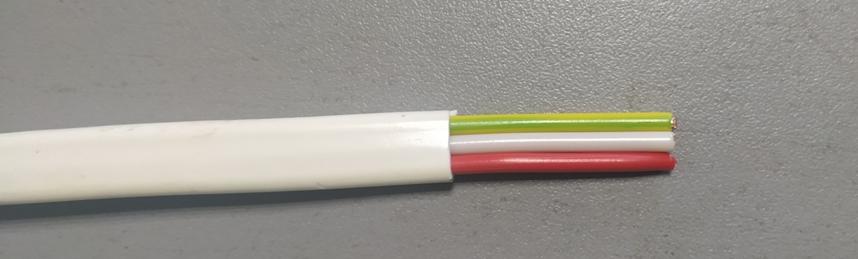
It is highly desirable for the first two points to use cable products with color or digital marking of cores. This reduces labor costs when disconnecting (no dialing and marking of cores are needed) and minimizes the likelihood of error. And for the cable that goes to the switching device, marking is not required - connection does not depend on phasing.
Usually for lighting arrangements cable is selected with copper conductors with a cross section of 1.5 sq. mm. Cables suitable for installation can be selected from the table.
| Cable | Number of cores | Additional properties |
| VVGp 2x1.5 | 2 | Flat |
| VVGp - NG 2x1.5 | 2 | Flat, non-flammable |
| VVG 3x1.5 | 3 | |
| NYY-J 3x1.5 | 3 | Incombustible |
| VVG - NG-Ls 3x1.5 | 3 | Non-flammable with low smoke emission |
The rules for the installation of electrical installations do not strictly regulate the installation sites of household switches. Only the distance to the gas pipes is precisely set. It must be at least 0.5 m.It is only recommended to install devices at a height of 1 m. The exception is children's institutions. There, the switching elements must be mounted out of the reach of children - 1.8 m, and the Rules are strict in this regard. Otherwise, you can be guided by the principles of safety and convenience. It is also necessary to determine the type of wiring (hidden or open) and, when choosing a place for mounting the device and a switch box, take into account the convenience and possibility of laying cable products.
The procedure for installing electrical appliances (step by step instructions)
If hidden wiring is chosen, it is necessary to equip recesses in the walls for installing a switch box and a socket box (a plastic box, sockets are also installed in a similar box). If it is open, then it is necessary to mount the linings (platforms) on which the devices will be installed. Next, you need to lay the cables in the chosen way, bring them into the socket and junction box. After that, you can proceed with the installation. The minimum set of tools that you need for this:
- wire cutters for shortening wires;
- fitter's knife for removing insulation;
- if available, an insulation stripper for stripping wires;
- a set of screwdrivers (at least two).
Perhaps something else will be required in the process of work.
First, the wire must be shortened to a length at which, after installation, it will be possible to close the junction box or install the device in the socket.
First, with a fitter's knife, you need to remove the upper sheath of the cable. This must be done carefully so as not to damage the insulation of the conductors (all the more, it is necessary not to touch the copper wires).
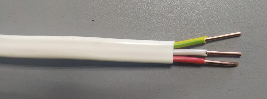
Next, you need to remove the insulation from the conductors to a length of 1-1.5 cm. This is also done with a fitter's knife, and if there is an insulation stripper, then it is even more convenient for them to work.
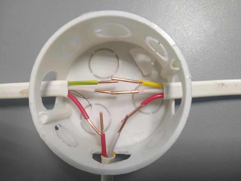
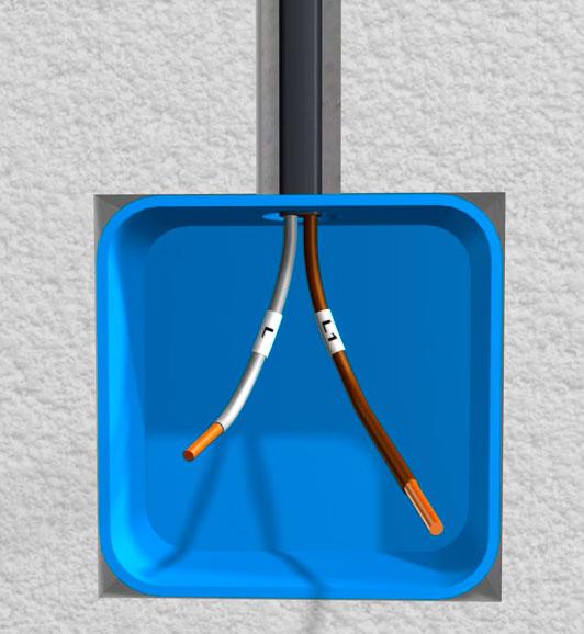
The cut ends are bent in the right direction. After that, you can start unplugging. Traditionally, connections in boxes are made by twisting. You can do this now, observing two rules:
- it is impossible to twist copper and aluminum conductors;
- all twists must be insulated (with insulating tape or plastic caps).
It is desirable to solder copper twists before insulation.
But in modern conditions, there are more convenient ways to connect conductors in a box. Various types of terminals are available on the market for wiring, both screw and clamp.
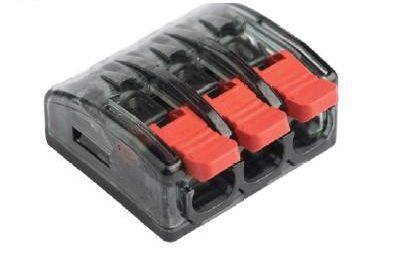
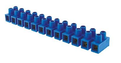
Installation is more accurate, reliable and safe.
Next, you can proceed to connect the actual switch. The first steps are the same:
- shorten the two-core cable;
- remove the outer shell;
- strip the insulation.
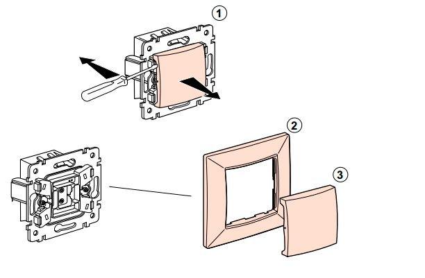
Then the device must be disassembled - carefully, so as not to break, remove the key and the decorative panel.
The next step is to insert the stripped ends of the conductive wires into the switch, fix them. The connection order does not matter, but usually the supply end is connected to the bottom terminal, the outgoing end to the top.
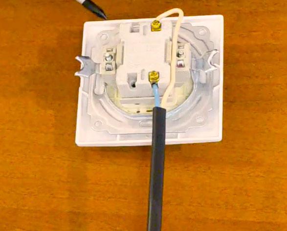
Then the switch is installed back into the box, the petals are unclenched, fixed to the surface with self-tapping screws.
After completing the wire connections, you must once again check the correctness of the mounted circuit. Lastly, a decorative frame with a key is installed.
On this, the connection of the electric light switch with one key is considered complete. You can apply voltage, then check the operation of the lighting.
Installation safety rules
The basic safety rule is that all work must be carried out with the power turned off. The absence of tension in the workplace must be guaranteed. One hundred percent confidence is provided by the production of technical measures:
- disconnection of voltage in the switchboard by opening the corresponding circuit breaker;
- disconnecting the outgoing conductor from the circuit breaker - this creates a visible break in the circuit and the erroneous supply of voltage by unauthorized persons will be excluded;
- control of the absence of voltage (with an indicator screwdriver, multimeter) directly at the workplace - due to errors in the marking or the absence of current changes in the switchboard circuit, the wrong circuit breaker or knife switch may be turned off.
Important! Safety rules when working in electrical installations also require grounding of live parts, as well as posting warning and protective posters. It is hard to imagine that someone doing homework will adhere to these rules. But there are never enough security measures - it is advisable to listen to these points.
Protective equipment is also an important part of ensuring safety when working with electrical appliances:
- dielectric gloves;
- dielectric carpets;
- hand insulated tool with an intact, unworn finish.
It will be useful to read: Connecting the switch with a single screwdriver.
And most importantly - it should be remembered that a live conductor looks exactly the same as a de-energized one. Power off must be controlled by devices.