How to connect a triple switch - wiring diagram
Along with single-key household switches, there are devices with two and three keys on sale. The latter cause the most questions from buyers. In fact, such devices are used in everyday life and in office premises. You can install and connect the triple switch yourself.
How a three-button switch works
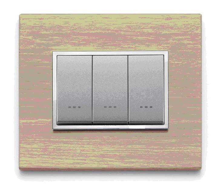
In appearance, the triple light switch looks like a regular one, but it has three movable panels. This determines the dimensions of the device - in most cases it is somewhat wider than one- and two-key counterparts.
Each controls its own group of contacts for switching on and off independently of the others. When manipulating the key, voltage is applied (and removed) to the dedicated load.
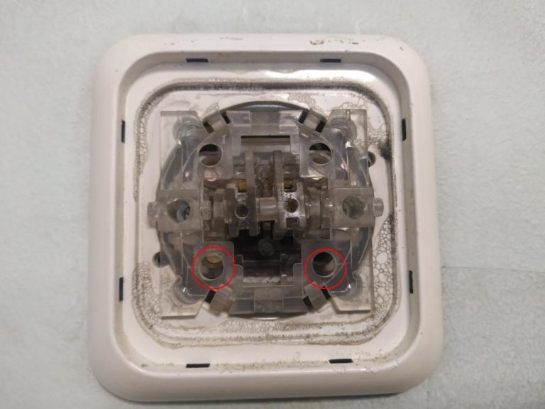
If you remove the keys, the switch mechanism with 3 moving elements will open.
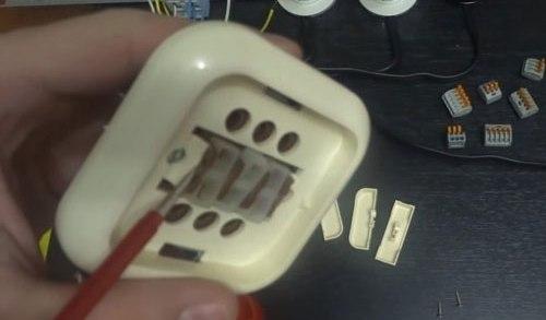
To install the switch at the installation site, you will also need to dismantle the decorative plastic frame. Switches of other designs have a similar design - for example, three-button ones.
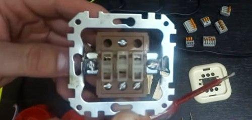
After that, the following will be available:
- expansion blade screws;
- terminals for connecting wires;
- holes for mounting the device on the surface.
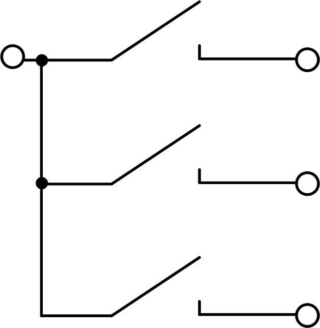
It can be seen that the device has a common contact on top, but this is not always the case. This must be taken into account when preparing for installation.
Scope of the three-keyboard
The most obvious use of a 3-panel fixture is to control three lights separately. Such a need in everyday life is rare. And in office or warehouse premises - a very real situation.
But in a house or apartment, multi-track chandeliers can be used. Although they are real power guzzlers (two 50-watt incandescent bulbs give less light flowthan one hundred watt), such lighting devices are widely used for aesthetic reasons. To increase the efficiency and comfort of operation of such lamps, you can use switches with several keys. By controlling not the chandelier as a whole, but individual lamps or groups of lamps, you can choose a convenient level of lighting and not waste electricity.
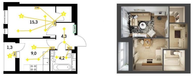
Selecting an installation location
If we turn to the seventh edition of the Electrical Installation Rules, it turns out that there are no strict conditions for installing household switches. Paragraph 7.1.51 recommends installing switching devices at the entrance at a height of 1 meter from the side of the handle. The rules only determine the minimum distance to gas pipelines. It must be at least 50 cm.But there are two exceptions:
- in children's institutions, switches must be mounted at a height of 1.8 m - out of reach of children;
- it is forbidden to install switching equipment in damp rooms (baths, baths, showers).
Otherwise, when choosing a place for installing three-key devices, you can be guided by your own ideas about convenience and safety.
Connection options
The obvious connection scheme for any three-gang switch is to control three different lamps. Each of the 3 contact groups switches its lamp independently of the others.
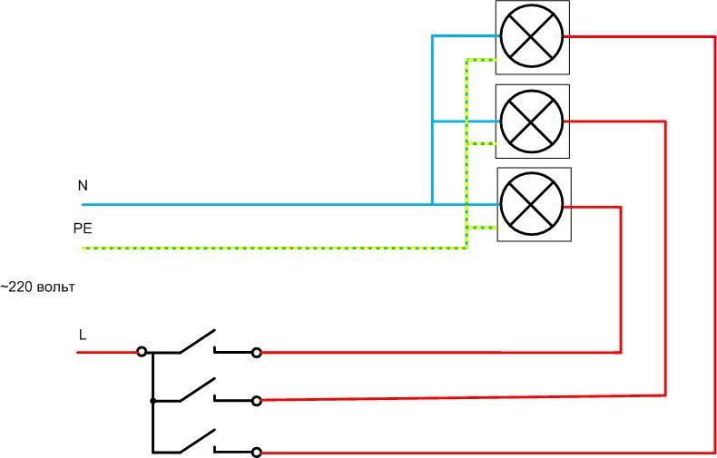
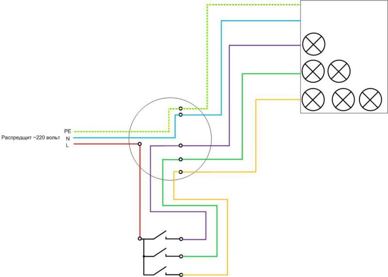
When connected through a junction box, the mounting topology looks like this:
From the figure it can be seen that to perform such an installation, you will need:
- three-core cable from the switchboard;
- three cables with three conductors to each consumer;
- four-wire cable from the junction box to the switchgear.
The junction box contains a large number of connections. Therefore, it is necessary to choose a junction box of the appropriate size.
Important! The PE conductor may not be present in TN-C power supply systems. It does not affect the operation of the circuit. But if it is, it must be laid and connected to the fixtures to the terminals marked with the letters PE or the earth symbol. This is a safety issue.
In the absence of a protective conductor, the number of cores in the supply and outgoing cables is reduced by one. A two-core cable will enter the box and exit to each consumer, but in any case, four conductors must be pulled to the switch.
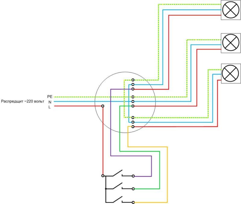
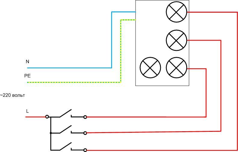
Another option for connecting a device with three independent groups of contacts is the control of multi-track chandeliers.
The difference between this scheme and the previous one:
- conductors PE and N do not stretch to each individual lamp, but to the lamp as a whole;
- each key can control both a single lamp and a group of lamps - depending on the internal circuit of the chandelier.
If you study the wiring diagram, it is obvious that in this case the installation in the junction box will be much less dense than in the previous case. The second difference is the list of cables. If the lighting is powered by a TN-S or TN-C-S network (with PE protective conductor), then the following will be required for wiring:
- 3-core cables from the switchboard to the box (two if there is no PE);
- five-core cable from the junction box to the chandelier.
As in the previous case, the switch is connected with a four-wire cable.
The video clearly shows the connection diagram with an example.
What is required for installation
Electrical installation will not work without a minimum set of tools:
- to strip the insulation you will need a fitter's knife;
- to shorten the conductors, you will need pliers;
- to check the absence of voltage, you will need an indicator screwdriver or a multimeter;
- for installation work - a set of screwdrivers.
If the connection in the junction box is made by twisting copper conductors, then it is advisable to solder the joints. To do this, you will need a soldering iron and consumables for it. Perhaps, in the process of work, there will be a need for other tools.
Preparatory work
Before starting the installation, determine the installation locations of the switches.If you plan to do hidden wiring, purchase recessed switches and sockets of the appropriate size (plastic boxes in which the device will be installed). With open wiring, linings must be placed at the installation sites of the devices.
Selection of conductor cross section
The cross section of the cable cores depends on the load and the laying method. Many years of experience show that the cross sections in 1.5 sq. mm in terms of throughput and mechanical strength is enough for 99+ percent of tasks organizing lighting. This size has become a certain standard. The wide distribution of LED products only confirms this thesis - the load in lighting networks does not increase. But if the case is non-standard, you can choose the cable according to the table.
| Conductor cross section, sq. mm | Permissible current, A | Permissible load at 220 V, W | ||
| Copper | Aluminum | Copper | Aluminum | |
| 1,5 | 19 | - | 4100 | - |
| 2,5 | 27 | 21 | 5900 | 4600 |
| 4 | 38 | 29 | 8300 | 6300 |
| 6 | 50 | 38 | 11000 | 8300 |
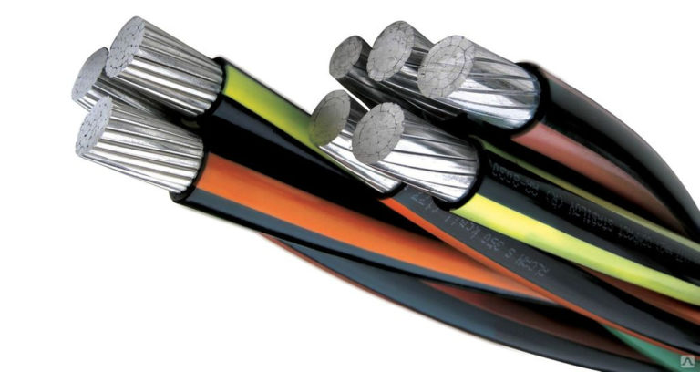
While aluminum conductors are permitted by regulation, only copper products are strongly recommended.
Next, you need to do the wiring - lay cable products in accordance with the selected scheme between all elements. It is better to use products with numbered and color-coded cores. If there is no such cable, you will have to carry out the continuity of the conductors and the marking of the cores yourself. Cables should be with a small margin of 10-15 cm in length. Upon completion of these works, you can proceed with the actual installation.
Safety requirements
When performing work, the main rule must be observed: all work is carried out on de-energized equipment. If the wiring is mounted from scratch, then the connection to the switchboard must be done last.
If the existing lighting system is being refurbished, it is necessary to ensure safety:
- turn off the corresponding circuit breaker in the shield, identifying it according to the diagram or marking;
- create a visible gap by disconnecting the wire from the terminal of the machine - this eliminates the erroneous supply of voltage;
- check the absence of voltage DIRECTLY AT THE WORK SITE.
Safety is enhanced by the use of insulated hand tools. Care must be taken that the insulation of the handles is not damaged or worn.
Switch mounting
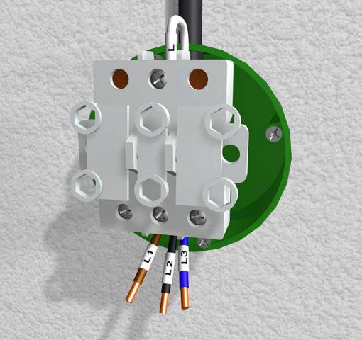
You can start assembling the circuit by installing the switch. The wires brought into the socket of the device must be shortened with wire cutters to a reasonable length - so that the device can be put in place. Next, use a utility knife to remove the upper sheath from the cable.
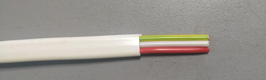
Then strip the insulation of the conductors with the same knife, if there is an insulation stripper, it will be more convenient to work. As a result, it should turn out like this:
Next, you need to look at which side the common terminal is located. It depends on what will be the on or off position of the switch.
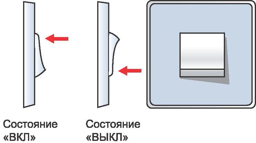
In Russia, it is customary for the “off” state to be when the bottom edge of the key is pressed. This tradition comes from the requirement of the rules that the switching element could not turn on under the influence of its own gravity. This applies, rather, to the knife switches, but the principle is well established. Another version - the rule comes from the condition that in a critical situation a person should be able to turn off the voltage by the action of the gravity of his body. Either way, it's a force of habit. In some countries, the exact opposite standard has been adopted, and it does not affect the actual operation of the lighting system.
Therefore, it is necessary to connect the switch so that it is convenient and familiar to control the light.
After that, you can install the device in the socket, open the petals, fix it with screws to the wall and put the plastic decorative elements in place.

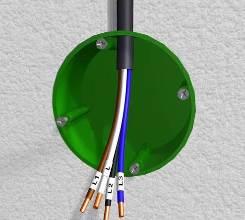
Junction box installation
If a three-key switch is used to switch three independent consumers, each of which has its own cable, then the conductors in the box should be arranged as follows:
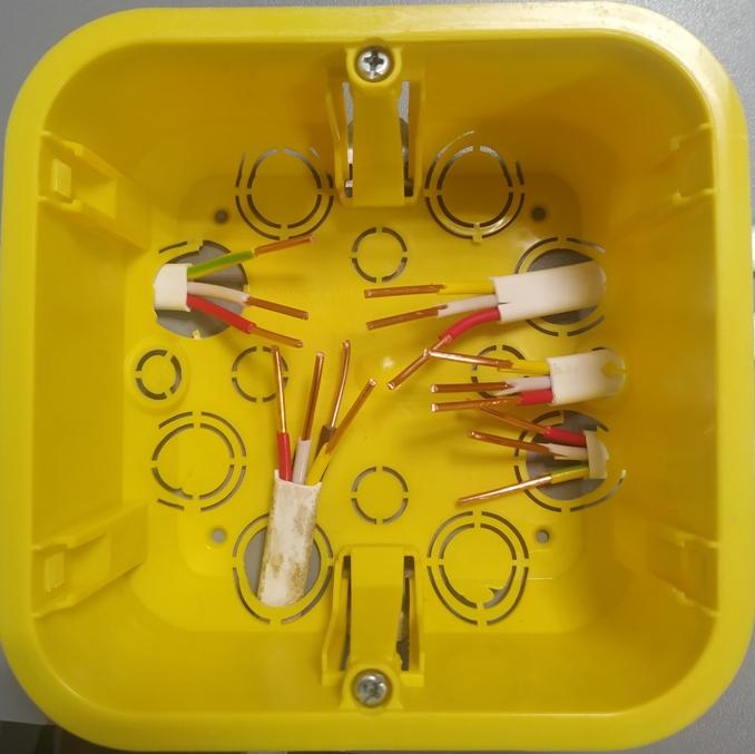
Conduct core connection according to the diagram above:
- connect PE conductors (yellow-green);
- neutral conductors (in this case, white, except for the one that goes to the switch) are also connected to each other;
- connect the red wire of the supply cable to the red (so as not to get confused) outgoing to the switch, this will be a common conductor;
- connect the white, brown, yellow wires of the four-core cable to the corresponding red core of the cables going to the luminaires.
Of course, the color of the cores does not affect the performance of the system, but observing the order of colors will minimize installation errors and facilitate possible repair in future.
If the three-keyboard controls the individual lamps of a multi-track chandelier, then the installation looks less cumbersome.
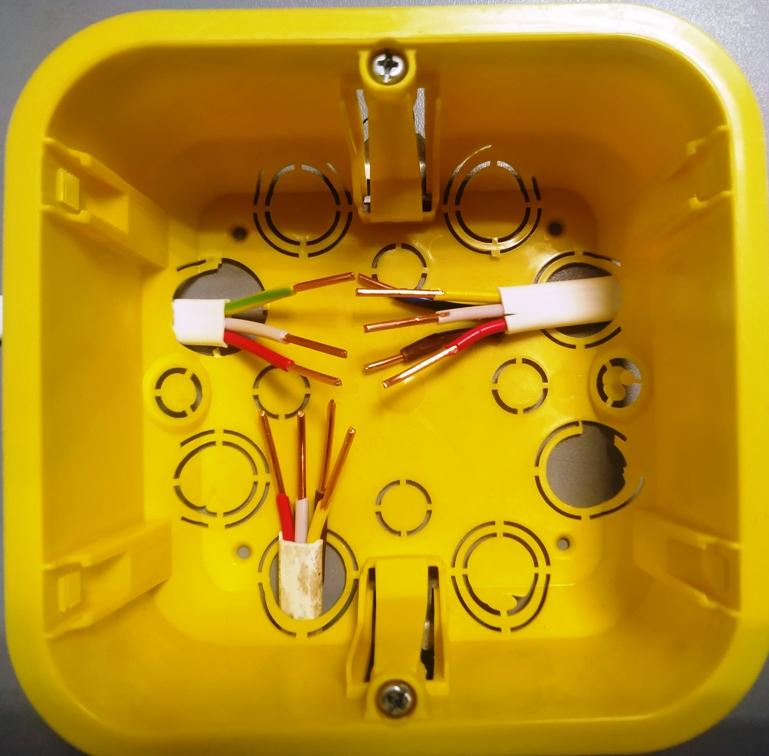
As in the previous case, the yellow-green (PE) and white (N) wires must be connected at the power cable and the one that goes to the chandelier - they go through the box in transit. The red cores of the supply cable and the outgoing cable to the switch are also connected. And the white, yellow and brown core can be connected to the cores of the same color of the outgoing five-core cable.
You can connect the conductors by twisting and then soldering (not necessary, but desirable - in the future it will reduce the likelihood of contact deterioration due to copper oxidation). At the end of the connection, the twisting points must be insulated.
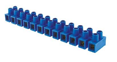
And it is better to connect the cores with special terminals - preferably screw type. Clamping is more convenient, but the reliability of such a contact is lower.

The video clip demonstrates both schematically and in action the way to connect the 3rd switch with a socket.
Typical mistakes
Installation errors may be due to incorrect connection of conductors. But the use of cables with marked cores, compliance with safety measures and care during installation should reduce the likelihood of such errors to zero. Then the lighting system will last for many years, delivering only a feeling of comfort.