How to connect a switch with a backlight indicator
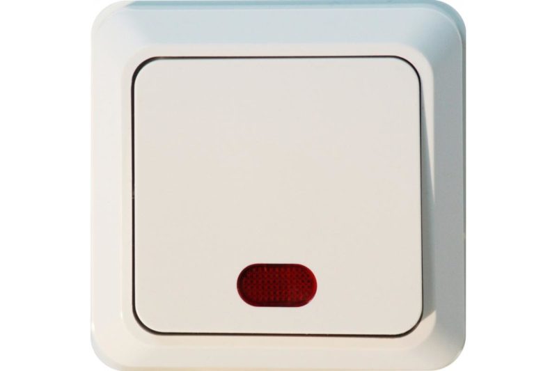
The backlit light switch has long been a part of everyday life. It is somewhat more convenient than usual - it is easy to find it in an apartment in the dark, it serves as an indicator for turning on the lighting, and in some cases its glow indicates that the lamp is working. This device works independently of knowledge about it, without additional interventions, but it is necessary to understand the principle of operation. For example, to consciously solve emerging problems.
Illuminated switch device
In most cases, the backlight circuit is arranged in the same way and consists of:
- ballast (quenching element) - resistor or capacitor;
- a light-emitting element - an LED (most often) or a neon light bulb.
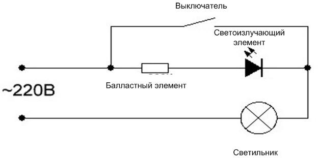
Chain elements are connected successively and connected in parallel with the contacts of the light switch.
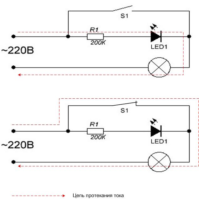
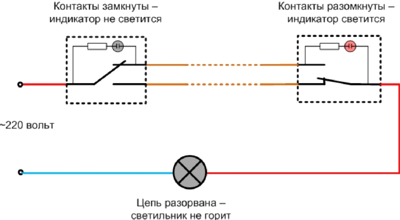
When the switch is open, the current follows the path "ballast - light emitting element - luminaire". The quenching element is selected so that the current in the circuit is sufficient to ignite the indication, but not enough to light the main lamp. If the switch is closed, its contacts shunt the backlight circuit, the current follows the path “contact group - lamp”, its strength is sufficient to ignite the lighting lamp.
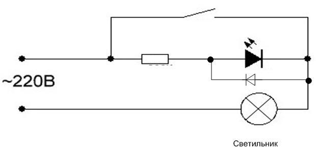
Most often, such a circuit is assembled on the basis of a light emitting diode, but it has a drawback. During the reverse half-wave of the sinusoidal voltage, the LED is off, its resistance is high. The mains voltage is divided between the lamp, LED and ballast in proportion to the resistance, and a large reverse voltage is applied to the LED. It is not designed for it, and its service life is reduced - through a relatively a short period of time LED will fail. To combat this effect parallel put a conventional diode in the opposite direction to the LED. During the reverse half-wave, it opens and the voltage is divided mostly between the main lamp and the ballast. Instead of a conventional diode, you can put a second LED and increase the brightness of the glow.
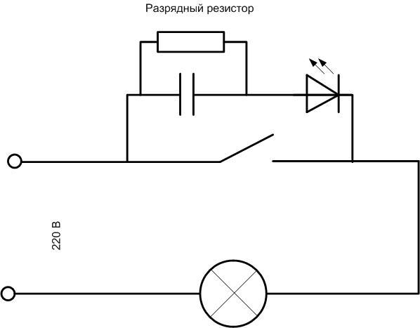
With ballast capacitor
A capacitor can be used as a quenching element. In AC circuits, the capacitance behaves like a resistance, and the value depends on the frequency (the higher it is, the lower the capacitance) and on the capacitance (as it increases, the reactance decreases).
The fundamental difference from the resistor is that active power is not dissipated on the capacitance, so we can talk about a certain amount of energy savings. How noticeable the savings with such a technical solution can be determined by calculations. Let the extinguisher resistor in the lighting circuit has a resistance of 220 kOhm (the resistance of the LED and the cold filament of the lamp can be neglected in the preliminary calculation). This means that the current through the resistor will be 1 mA, and 220 milliwatts of power will be dissipated on it. In one hour, the cost of electricity for lighting will be 220 milliwatt-hours. Let the lighting be turned off for 20 hours a day. Then the costs of the cost of electricity for different periods of time can be summarized in a table.
| Period | Electricity consumption | The cost of a kilowatt-hour for the population (average value), $*kW*h | Electricity costs for the period, $ |
|---|---|---|---|
| Day | 4400 milliwatt hours=0.0044 kWh | 3,5 | less than a penny |
| Month | 132000 milliwatt-hours=0.0132 kWh | 0,05 | |
| Year | 1584000 milliwatt-hours = 0.1584 kWh | 0,55 |
When using a capacitor instead of a resistor, a corresponding amount is saved. Each consumer evaluates the size and value of profit for himself. But it must be borne in mind that for this money it receives an increase in dimensions (a capacitor for a voltage of 400 volts or more is quite large in size) and the need (in this case, desirability) of an additional resistor in parallel with the capacitance for its rapid discharge. In such circuits, they also put a resistor that limits the current of the primary charge of the capacitor, but in such a circuit, a lighting device plays its role.
With a neon light
As a light emitting element, you can use neon lamp.
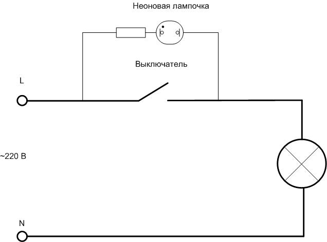
It works at even lower currents - from 0.2 A. The advantages of this light emitting element:
- not afraid of reverse voltage, you can not install additional parts;
- less current - less power dissipation on the ballast, smaller dimensions, less heating.
The reduced current also reduces the chance of flashing LED lights with the switch in the off position.
Installation and connection of illuminated switching devices
The indication chain has almost no effect on the operation of the switch, and for its operation it does not matter which side the phase wire will come from. Therefore, for standard key devices, the presence of illumination does not change anything. The device is also mounted in a break in the phase wire. The supply core is also connected to it, and the conductors depart according to the number of loads. But there are a few points.
Installation of switches with one key
Installation and connection of single-key instrumentation has no special features. But keep in mind that the indicator can be located both at the top of the panel of the device, and at the bottom (sometimes in the middle). Therefore, it makes no sense to focus on the position of the lamp in order to determine the on position of the keys.

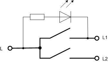
Features of connecting a device with two keys
At connecting a two-key light switch with backlight, it must be borne in mind that in most cases only one pair of contacts is equipped with an indication. Therefore, when one of the keys is turned on, the light emitting element will go out and the device will remain without indication. It does not matter if the device switches two lighting systems in one room.But it may matter if the switch controls the light of two different rooms (toilet and bathroom in a separate bathroom).
Connecting a through switch with an indication circuit
For pass-through device the described principle of circuit deshunting is of little use. If the lighting circuit is broken, then the contacts of one switch may be closed. And if the backlight is installed on only one pair of contacts (like a two-gang switch), then when the light is off, this circuit will be shunted.
To eliminate this shortcoming, it is necessary to put illuminating elements on each pair of contacts and use two light emitters. This requires additional space inside the device and design frills for the execution of the front panel. Therefore, parallel circuits for switching on radiating elements are used for mid-flight switches.
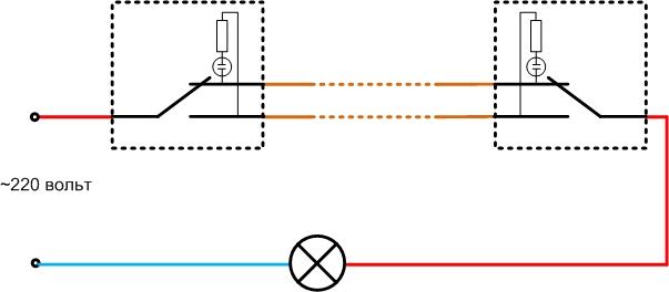
In the first diagram, additional elements are connected in parallel with fixed contacts. In this case, when the circuit is broken and the lighting is off, both indicators will light up. With the main circuit assembled, both bulbs will be unpowered.
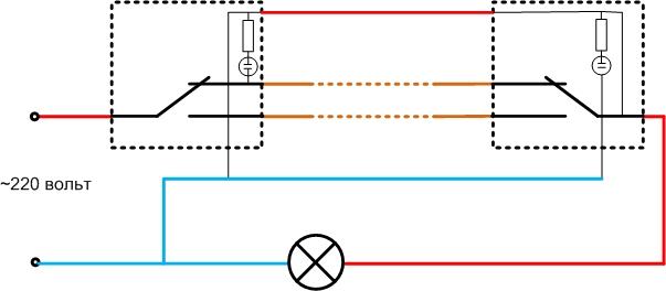
Another option is to indicate the inclusion. In this case, the indicator lights are on when the lamp is on. The disadvantages of such a connection are:
- the need to lay a third wire between the mid-flight switches;
- the need to lay a neutral wire N to the switches.
Yes, and the practical benefits of indicating the on state of lamps is questionable.These indicators will light up even if the lamp is not installed in the lamp or the cable is forgotten to be connected to it.
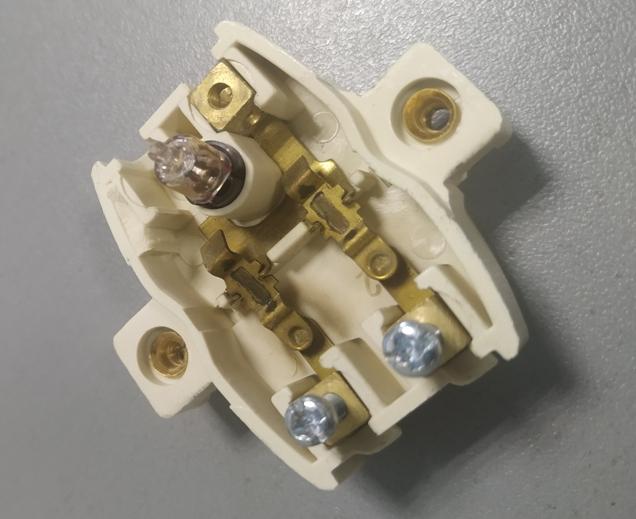
We look at the visual connection of the wires.
Disabling the indication circuit
If necessary, the highlight elements can be removed. Such a need may arise, for example, in the event of an unpleasant flashing of the LED or energy saving lampscaused by the flow of a small current through the limiting element. This problem can be solved in other ways, but it may happen that removing the indication is the only way out. In this case, you will need small pliers.
The work on removing the indication chain can be carried out on a dismantled device, or you can not dismantle the switch with an LED, just remove the decorative plastic parts. In any case, before starting work, it is necessary to turn off the power supply to the lighting network using the switchgear in the switchboard. After that, make sure that there is no voltage directly at the switch.
After gaining access to the internal device of the device, it is enough to bite any output of the LED. This will open the indication circuit. But it is better to completely remove the LED or neon to avoid accidental short circuits with cut leads.
Perhaps removing the plastic parts will not be enough to gain access to the backlight chain. In this case, it will be necessary to continue dismantling device. In most cases, this can not be done without dismantling the switch from the installation site.
In the video, the LED is removed from the switch very quickly.
DIY illuminated switch
The lighting circuit can be assembled and installed by yourself.This is especially true for old-style switches - they do not have illuminating chains, but there is enough space inside to place the elements and enough space on the front panel to install a light bulb. On modern switches, the problem arises of finding a place to install a light emitter, so in many cases it is easier to buy the appropriate device. But it can be difficult to purchase, for example, a three-gang backlit switch. Or you need a double switch with an indication for each pair of contacts. Therefore, the lighting circuit will have to be done independently.
Basically, the problem of creating a lighting chain comes down to choosing a scheme, calculating and selecting a ballast.
If a circuit with a quenching resistor is selected, then it is calculated as follows:
- The voltage drop across the ballast is determined Ubal=Unetwork-Ulamps. On an open LED, no more than 3 volts will drop, so for practical calculations it can be assumed that all mains voltage will be applied to the resistor Ubal=310 volt (it is necessary to take the amplitude, and not the effective value of 220 volts). For a neon lamp, one must be guided by the ignition voltage, and it ranges from tens to hundreds of volts. If this parameter is unknown for a particular lamp, it is necessary to set the voltage to 150 volts, and the quenching element will drop Ubal=310-150=160 volt.
- The operating current of the radiating element is selected. For LED, you can choose Iwork=1..3 mA, for neon - Iwork=0.5..1 mA.
- The ballast resistance will be Rbal \u003d Unetwork / Iwork. If the current is in milliamps, then the resistance will be in kiloohms.
- Ballast resistor power Pbal=Ubal*Irab. If the circuit does not use an additional diode, the resulting value can be divided by two.
If a capacitor is selected as a voltage damping element, then the calculation is made according to the formula C \u003d 4.45 * Irab / (U-Ud), where:
- FROM is the required capacitance in µF;
- Islave - operating current of the LED;
- U-Ud - the difference between the supply voltage and the voltage drop across the light emitting element (ignition voltage of a neon lamp).
The closest standard capacitor value is selected. It is advisable to round down, but make sure that the operating current does not decrease excessively. Any semiconductor device can be used as a diode) for a reverse voltage of at least 400 V (the current does not play a decisive role). You can choose the appropriate size from the series 1N400X.
Next, you need to drill a hole in the selected location of the switch panel, glue the light element, assemble the indication chain, connect it to the terminals of the switching device. After that, you can connect the switch with the indicator installed in place and try out the operation of the backlight.