Homemade motion sensors to turn on the lights
The motion sensor can be purchased at the store. But if you have some free time, little skills and knowledge, you can make such a sensor yourself. This will save some money and provide a pleasant pastime for technical creativity.
Which sensor can be made independently
There are several types of motion sensors, and each type, in principle, can be made independently. But ultrasonic and radio frequency sensors are difficult to manufacture, require special skills and instruments for adjustment. Therefore, it is easier to manufacture capacitive and infrared type sensors.
Devices and materials
To make a motion detector you will need:
- soldering iron and consumables;
- connecting wires;
- small metalwork tool;
- multimeter.
You will also need a breadboard to make the sensor.And it's also nice to have an oscilloscope to monitor the performance of a device based on an RF generator.
capacitive type sensor
These sensors respond to changes in electrical capacitance. On the Internet, in everyday life, and even in technical documentation, the erroneous term “volumetric sensor” is often used. This concept arose due to an incorrect association between geometric capacity and volume. In fact, the sensor responds to the electrical capacitance of space. Volume, as a geometric parameter, does not play any role here.
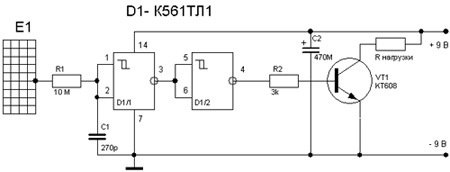
The motion sensor is really do-it-yourself. A simple capacitive relay can be assembled on just one chip. To construct the sensor, a K561TL1 Schmitt trigger was used. The antenna is a wire or a rod several tens of centimeters long, or another conductive structure of similar dimensions (metal mesh, etc.). When a person approaches, the capacitance between the pin and the floor increases, the voltage at pins 1.2 of the microcircuit increases. When the threshold is reached, the trigger "overturns", the transistor opens through the buffer element D1 / 2 and powers the load. It could be a low voltage relay.
The disadvantage of such simple sensors is insufficient sensitivity. For its operation, it is required that a person be at a distance of several tens, or even units of centimeters, from the antenna. Circuits with an RF generator are more sensitive, but they are more complicated. Winding parts can also be a problem. In most cases, you will have to make them yourself.
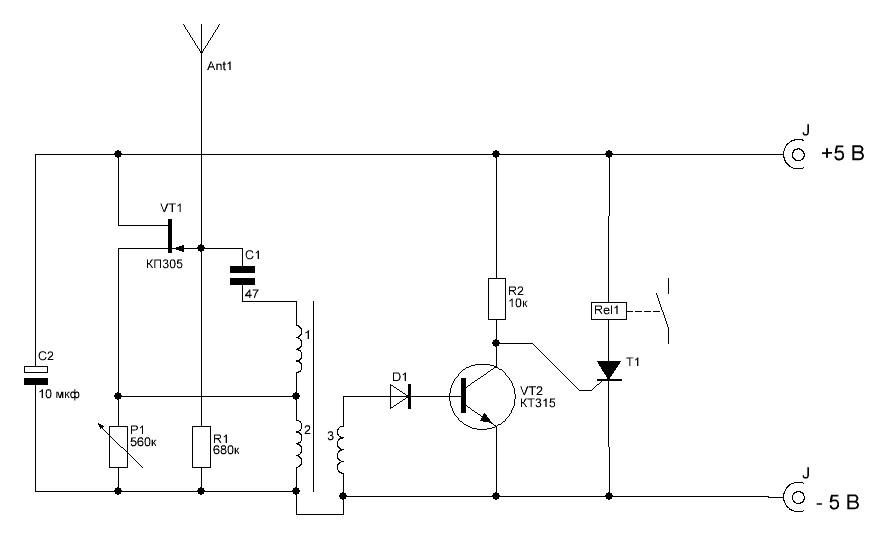
The advantage of this circuit is the possibility of using a ready-made transformer from a transistor receiver ST1-A.It is included in the generator circuit (inductive "three-point") on the transistor VT1. Resistor R1 regulates the depth of feedback, achieving the appearance of oscillations. Oscillations in the generator are transformed into winding III, rectified by the diode VD1. The rectified voltage opens the transistor VT2, it supplies a positive potential to the control electrode of the thyristor. The thyristor, opening, energizes relay K1, the contacts of which can be used to connect an alarm.
The antenna is a piece of wire about 0.5 meters long. When a person approaches (at a distance of 1.5-2 meters), the capacitance introduced by his body into the generator circuit disrupts the oscillations. The voltage on the winding III disappears, the transistor closes, the thyristor turns off, the relay is de-energized.
Assembly of the detector
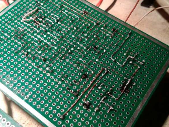
To assemble a homemade sensor, you can make a printed circuit board. For example, the LUT method. The technology is simple and easy to master. But if the manufacture of the sensor is one-time, it makes no sense to waste time on experiments. The best solution would be to use a breadboard circuit board.
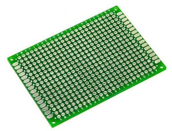
It is a board with metalized holes with a standard pitch, into which electronic components can be soldered. The connection to the circuit is made by soldering the conductors to the corresponding points.
You can also use a solderless breadboard, but the reliability of the connections on it is much lower. This option is best left for experimentation and honing the art of circuitry.
Checking the health of electronic components
First of all, it is necessary to inspect the selected parts.If they were not in use, there are no traces of soldering, and there is no mechanical damage, then further verification does not make much sense. The probability that the components are working is 99 percent. Otherwise, it's a good idea to check the details:
- resistors are called with a multimeter - it should show the nominal resistance (taking into account the accuracy class of the resistor);
- winding parts ring for the absence of a break;
- small capacitors with a tester can only be checked for the absence of a short circuit;
- large capacitors can be checked with a dial multimeter in the resistance test mode - the arrow should twitch to the right, and then slowly return to zero (left);
- diodes are checked with a tester in the diode test mode - in one position the resistance should be infinite, in the other the multimeter will show some value (depending on the type of diode);
- bipolar transistors are tested in the same mode as two diodes - between the base and collector and between the base and emitter.
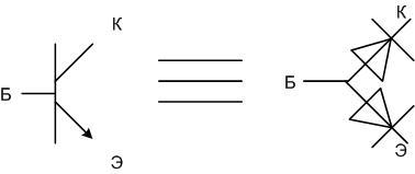
Important! Field-effect transistors with a p-n junction (KP305, etc.) are checked in the same way (gate-source, gate-drain), but the multimeter will show some resistance between the drain and source (infinity for a bipolar one).
Microcircuits cannot be checked with a multimeter.
Board marking and trimming
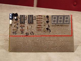
Further, all components must be placed on the board in such a way as to optimize future connections. To do this, they must be placed in one corner or near one side. Then draw lines, remove elements and cut off the excess.This can be omitted, but then the board will take up more space and require a larger case (and it will be needed if the detector is installed outdoors).
The edges of the board must be processed with a file. Doesn't affect performance, but looks better.
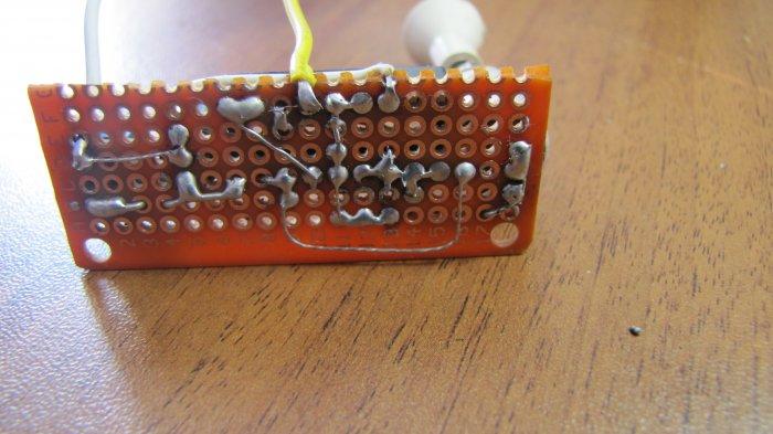
Then the parts are inserted back, soldered into the holes and connected with conductors according to the diagram.
The video shows how to make a motion sensor to turn on the light from the module for arduino.
Infrared sensor and Arduino
You can make a good motion sensor on the Arduino platform. The electronic "constructor" includes a PIR sensor module HC-SR501. It includes an infrared detector that remotely responds to temperature changes with a controller.
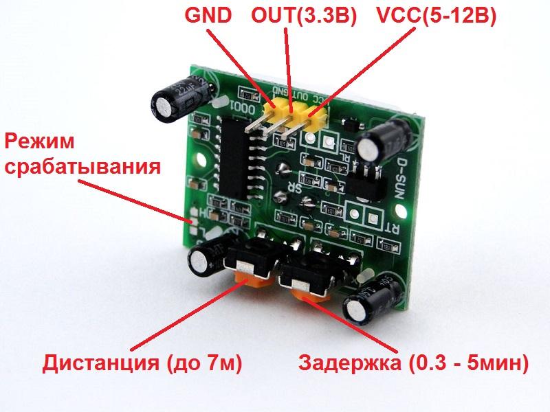
The module is fully compatible with the main board and is connected to it with three wires.
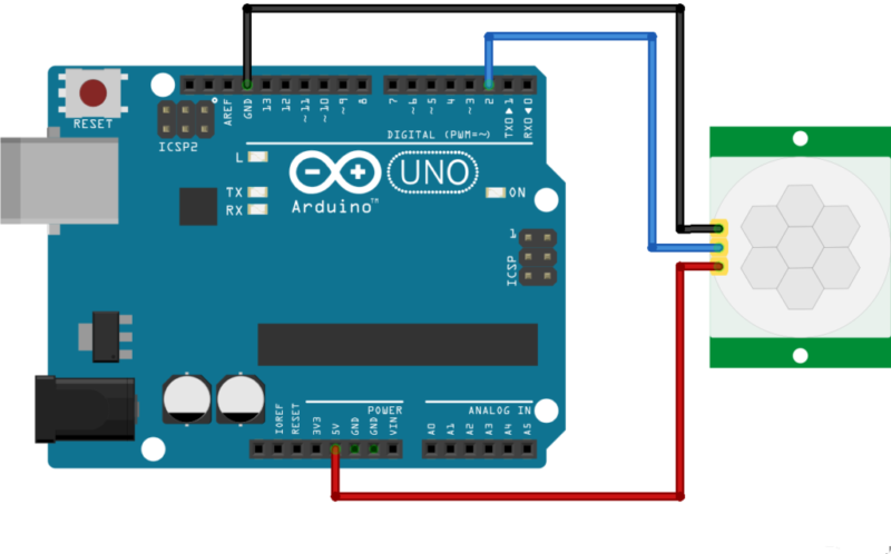
| IR module output | GND | VCC | OUT |
| Arduino Uno Pinout | GND | +5V | 2 |
To make the system work, you need to upload the following sketch to Arduino:
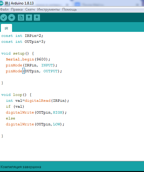
First, constants are set that determine the purpose of the pins of the main board:
const int IRPin=2
The IRPin constant means the pin number for input from the sensor, it is assigned the value 2.
const int OUTpin=3
The OUTpin constant means the pin number for the output to the executive relay, it is assigned the value 3.
The void setup() section sets:
- Serial.begin(9600) - speed of exchange with the computer;
- pinMode(IRPin, INPUT) – pin 2 is assigned as an input;
- pinMode(OUTpin, OUTPUT) – pin 3 is assigned as an output.
In the void loop section of the constant val the value of the input from the sensor is assigned (zero or one). Further, depending on the value of the constant, output 3 appears high or low.
Checking the performance and configuring sensors
Before using the assembled sensor for the first time, carefully check the installation. If no errors are found, voltage can be applied. Within a few seconds after turning on the power, it is necessary to check the absence of local overheating and smoke. If the "smoke test" is passed, you can check the performance of the sensors. Sensors on the Schmitt trigger and Arduino do not require adjustment. It is only necessary to simulate the presence of an object near the sensor (raising a hand) and control the change in the signal at the output. A detector based on an RF generator requires setting the start time of generation using potentiometer P1. You can control the onset of oscillations with an oscilloscope or by clicking a relay.
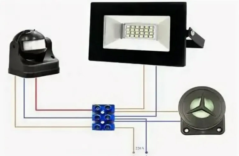
Load connection
If the sensor is operational, a load can be connected to it. It can be the input of another electronic device (beeper), but often the detector is required to control lighting. The problem is that the load capacity of the output of a homemade sensor does not allow you to connect even low-power lamps directly. That's why an intermediate key in the form of a relay is required.
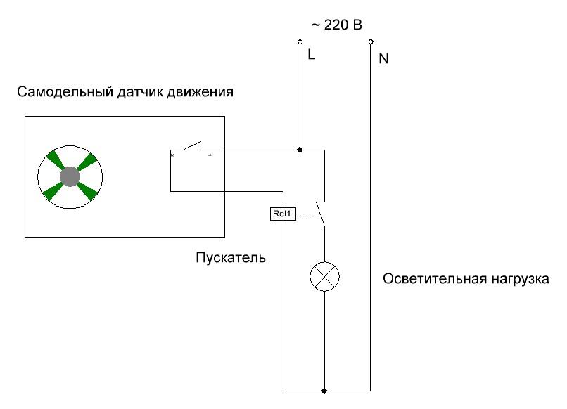
Before connecting the starter, make sure that the contacts of the sensor output relay allow you to switch the voltage of 220 volts. Otherwise, you will have to install an additional relay.
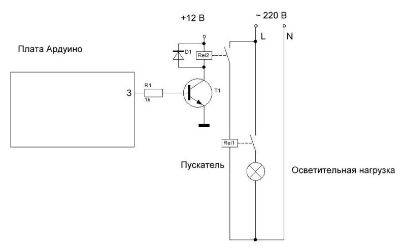
The Arduino output is so low power that it cannot drive a relay or starter directly. You will need an additional relay with a transistor switch.
If all the stages of assembly and configuration were successful, you can install the sensor permanently, make the final connection and enjoy the well-functioning automation.