How to connect a light bulb through a switch - diagrams
The light switch is a common household appliance. It is designed to close, open (and in some cases switch) the electrical lighting circuit. You can connect the switch to the light bulb yourself, but it does not hurt to first familiarize yourself with the proposed materials.
Varieties of light switches
Household switching devices can be classified according to different criteria. First of all, they are divided according to purpose. It is determined by the type of contact groups, their number. The most common devices are key.They have a contact group for closing-opening the electrical circuit. By the number of contact groups, such devices are divided into:
- single-key - with one contact group;
- two-key - with two independent groups;
- three-key - with three.
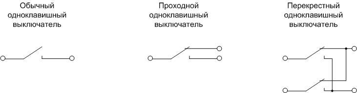
There are also walk-through and cross fixtures for creating light control schemes from multiple points.
They can be divided according to the mode of action:
- keyboards;
- push-button - with a button without fixing to control the light through impulse relays;
- rotary - to turn on the lighting, the control body must be turned;
- touch, remote controlled, etc. - to create systems like "Smart House».
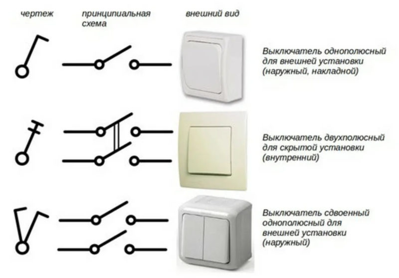
By type of installation, switches are divided into:
- external - used for open or hidden wiring;
- built-in - used for hidden wiring.
According to the degree of protection, the switches are divided into devices for indoor installation and outdoor installation (IP not less than 44). Also, when choosing, you need to pay attention to the rated current - it should overlap the current of the intended load with a margin.
Preparation for work, selection of equipment
To successfully connect an electric light bulb, certain materials and tools are required. Without this, there is no need to talk about any quality that determines the durability of the system.
A set of necessary tools
To complete the installation you will need:
- fitter's knife for removing insulation;
- if there is an insulation stripper, it will come in handy for stripping individual conductors;
- cutters will be required to shorten cables, wires to the required length;
- for the installation of electrical appliances you will need a set of screwdrivers;
- if soldering of twists or tinning of stripped wire sections is expected, you will need an electric soldering iron with a set of consumables (flux, solder).

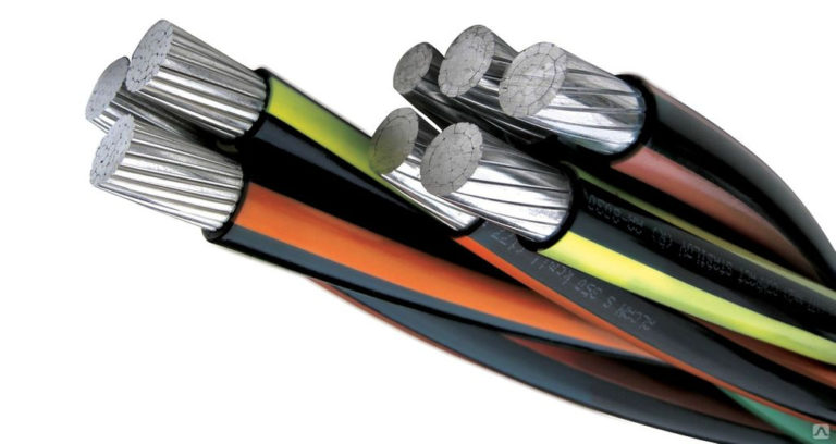
Conductor products
When choosing a cable for a lighting system, one must take as a basic rule - no aluminum. The relative cheapness of aluminum conductor products is balanced by potential problems in further operation:
- the ductility of this metal leads to deterioration of the contacts in the clamping terminals, they will need to be periodically tightened;
- its fragility will lead to problems during subsequent repairs;
- the tendency to oxidize in air will also not improve contact (copper is also not free from this drawback, but here the problem can be radically solved by tinning the cleaned areas).
In addition, the resistivity of aluminum is 1.7 times higher than that of copper. Therefore, you will have to choose conductors of a larger cross section. It also offsets some financial savings.
As for the cross-section of the cores, it is selected according to the economic current density and checked for thermal and dynamic resistance to short-circuit currents. It is also required that the voltage drop on the supply conductors does not exceed 5% for the farthest consumer. But in most cases, you do not need to do calculations. Years of experience shows that a cross section of 1.5 sq. mm (for copper!) is 99+% usable cases of arranging lighting networks. Only in rare situations (extra-long lines, etc.) is it necessary to check for voltage drop and resistance of the phase-zero loop.The cross section may need to be increased. But for standard cases, the best option is to use the VVG-1.5 cable with the appropriate number of cores or its foreign and domestic counterparts.
For arranging wiring, you can not use products with soft stranded conductors, as well as PUNP cable and its analogues.
Conductor marking
For electrical work, it is more convenient to use cables, all conductors of which are marked. It is performed using insulation of various colors. For three-core cables used in single-phase 220 volt networks, the color marking indicated in the table has become a kind of standard.
| Purpose of the conductor | Designation on the diagrams | Color |
|---|---|---|
| phase | L | Red, brown, white |
| Null | N | Blue |
| Protective | PE | yellow green |
Failure to comply with color matching will not lead to a disaster or loss of network performance, but to confusion and installation errors - almost 100%.
A less common option is digital marking. Numbers from one to the maximum number of cores in the cable are applied to the insulation along the entire length of the conductor. If an unmarked cable is used, after laying and cutting it, you must ring it out with a multimeter or in another way and mark the cores yourself.
Connection of copper and aluminum conductors
It is a well-known fact that conductors should not be in direct contact in electrical wiring. Copper and aluminum have a significant difference in electrochemical potential, so an EMF will occur at the point of their contact.It is insignificant, but over a long service life, the current constantly flowing through the junction, when interacting with atmospheric moisture, will cause electrochemical corrosion. It leads to the formation of an oxide film, deterioration of contact and local overheating, and these effects will only increase with time. As a result, the contact point will burn out, or even the ignition of the insulation of conductors or other nearby objects.
Therefore, copper and aluminum wires can only be connected via terminals made of steel. Better yet, forget about the very possibility of making aluminum wiring and making it only from copper conductors.
Junction box selection
If the installation is carried out in a residential area, the choice of a junction box comes down to buying a plastic box suitable for:
- outdoor wiring;
- concealed wiring;
- installation on a plasterboard partition.

But if the junction box will be installed indoors with special conditions (production, etc.) or outdoors, then you need to pay attention to the degree of protection against moisture and dust IP, and select a product that meets the operating conditions.
Wiring and connections
The key point when connecting a luminaire through any switch is the quality of electrical connections. If this job is done poorly, everything else is meaningless.
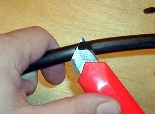
Removing insulation
First of all, the cables must be shortened to the required length. You can do this with pliers. Then remove the insulation in the desired areas.
The cable contains at least two layers of insulation:
- external - common to all conductors;
- internal - individual for each core.
Both layers can be removed with a fitter's knife - cut the plastic along the ring, trying not to touch the veins, and remove the resulting piece.
It is even better to use special strippers for external and internal insulation.

Their advantage is that you can adjust the depth of the notch so as not to damage the cores. In addition, the wire after cutting looks neater.
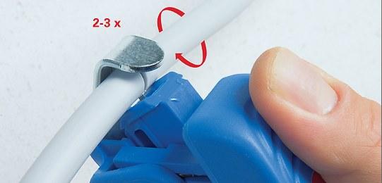
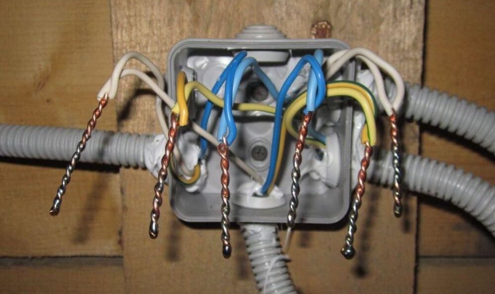
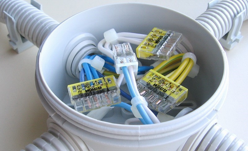
Stranding
When disconnecting the wires in the junction box, you can use the clamp terminals. But there is a reasonable opinion that this good, convenient and progressive method does not guarantee reliable contact for many years (especially at high currents), so the good old twist will not leave the stage for a long time.
Before starting work, it is worth remembering once again that it is impossible to twist copper and aluminum conductors. It is possible to twist aluminum together, but the fragility of this metal imposes restrictions on this method. Therefore, it is optimal to twist copper conductors together. In addition, copper is easily soldered, so it is recommended to solder the contact point after twisting. This will protect the surface of the conductor from oxidation and give the connection mechanical strength.
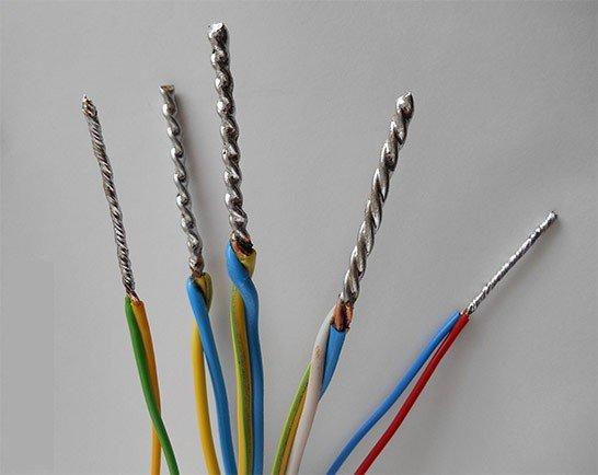
Another option is to weld the ends of the twisted wires. This will require an industrial or homemade welding machine.
Stranded wires can be crimped, but this will require copper sleeves, special tools and skills.

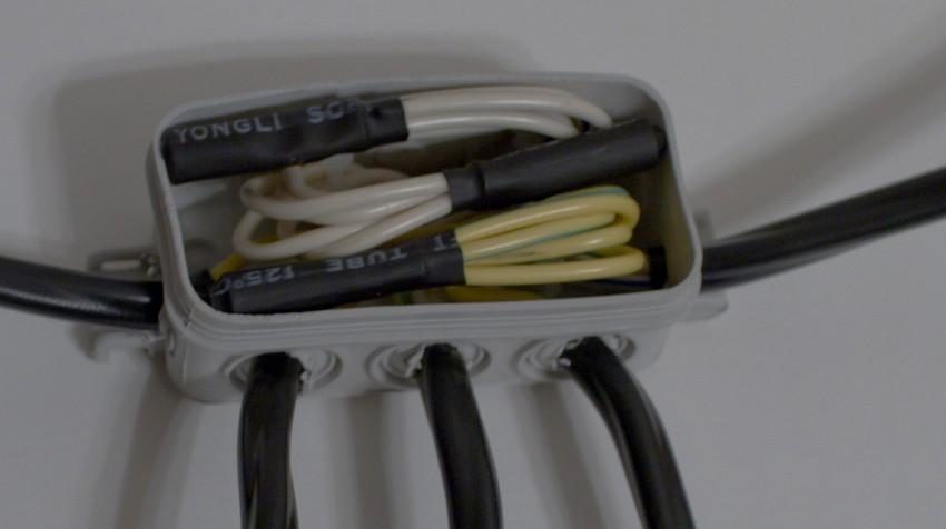
In any case, the places of twisting must be insulated. In addition to electrical tape, special plastic caps are suitable. When using heat shrink, remember that the sharp ends of the wires can damage the superimposed thin tube. Therefore, it is advisable to use heat shrink in two layers.
A good alternative to spring terminals and twisting is the use of screw terminals. At the same time, the problem of contact between aluminum and copper is solved. But they take up more space in the junction box and installation is more laborious.
wall chasing
If the hidden wiring option is chosen, before starting the installation, it is necessary to make channels in the wall for laying cable products - strobes (the term strobes is found in the technical and regulatory literature). It is best to make them with a special power tool - a wall chaser. If it is not there, a grinder or puncher will do. As a last resort - a hammer and a chisel.
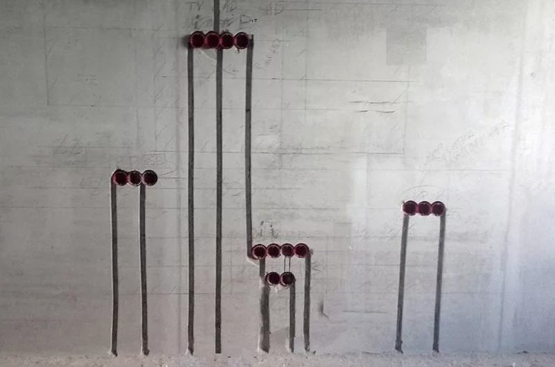
When working, several restrictions must be observed:
- strobes can be laid strictly horizontally or vertically (at an angle of 0 or 90 degrees);
- you cannot cut horizontal channels on load-bearing walls.
The rest of the rules can be found in SP 76.13330.2016 (current edition of SNiP 3.05.06-85).
Then, in pre-selected places, it is necessary to equip recesses for installing switch boxes and socket boxes. This is done with a drill bit.
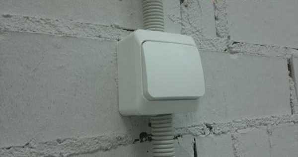
Switch installation
With open wiring, the switch is installed on a lining panel or directly on the wall.
If the built-in option is selected, the socket box is first mounted and the cable is led out into it.
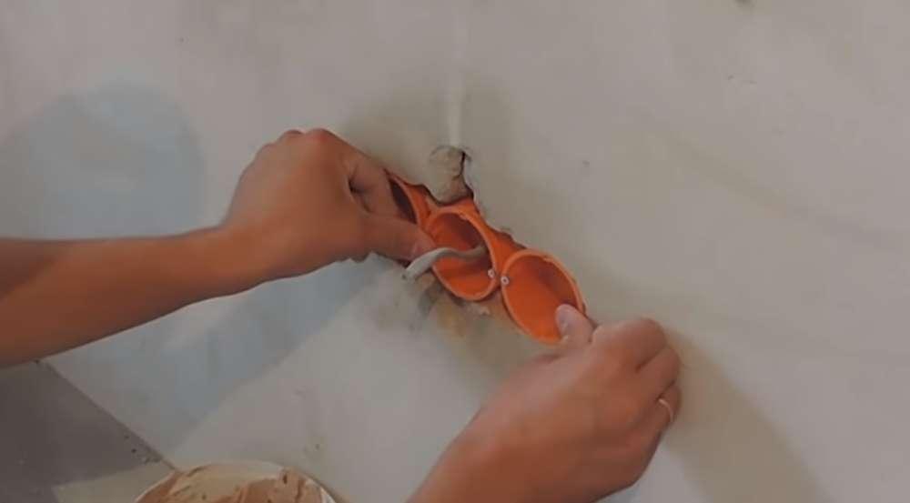
Next, the cable is cut, as indicated above: it must be shortened and stripped of insulation.
Then, decorative details should be removed from the switch - the frame and keys.
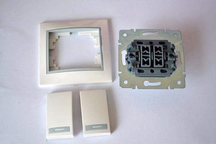
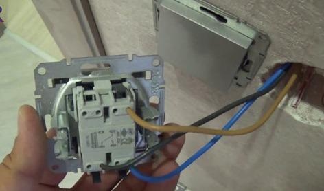
Next, you need to connect the wires to the terminals. If the terminals are clamping, then the cores are simply inserted into them. If screw - they must be securely tightened with a screwdriver.
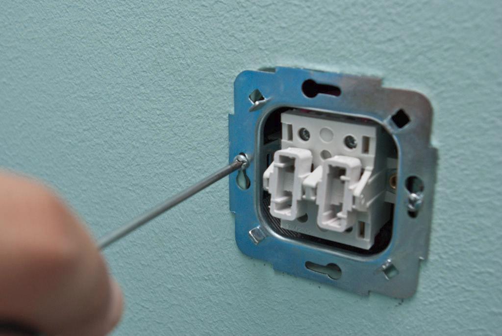
Next, tighten the bolts of the expanding petals until the device is completely fixed in the socket and, if provided by the design, attach it to the wall with self-tapping screws.
After that, you can install the plastic parts back, apply voltage and try out the operation of the circuit.
More detailed instructions for installing the switch are described separate article.
Connection using junction box
Connection using a junction box is always recommended, except for the implementation of a multi-point lighting control scheme using a series connection. checkpoints and cross switches. In this case, it is better to lay cables and connect with a loop.
If mounting with a junction box is selected, then it is carried out according to the following principles:
- from the switchboard to the box, a two-core supply cable is laid (three-core, if there is a ground conductor) with phase and neutral wires;
- each luminaire has its own two-core cable (three-core in networks TN-S or TN-C-S) with veins L and N (PE);
- conductors N and PE follow in transit through the box to the lamps, if necessary, they branch according to the number of lamps;
- the phase conductor has a break, a switching device is connected to it according to the diagram;
- a cable with the appropriate number of cores is lowered to the switch.
Conductor PE in the presence of protective grounding, it is necessary to lay it, even if lamps without grounding are used (for example, with incandescent lamps). This will help to avoid problems during network reconstruction in the future.
We recommend to see clearly how the masters do it.
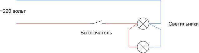
Connecting a switch with lamps connected in parallel
Such an inclusion has no fundamental differences from the usual one - the phase and neutral wires are pulled to the first lamp according to the scheme, from there to the second one and so on. If one lamp burns out, the rest will remain in operation. It is only worth remembering that in such a scheme the switch must be rated for the total current of all lamps.
Read also: How to connect light bulbs in series and parallel
Schematic connection examples
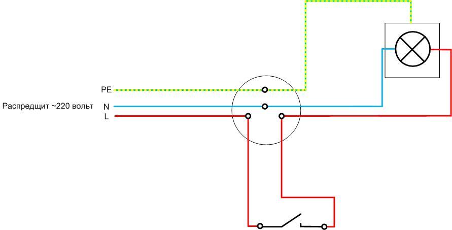
As a simple example, consider what the circuit looks like connecting a switch to a light bulb (protective grounding available). A three-core cable is inserted from the shield into the box, and a three-core cable also goes to the lamp. The phase conductor is broken, a switching device is connected to the gap using a two-wire cable.
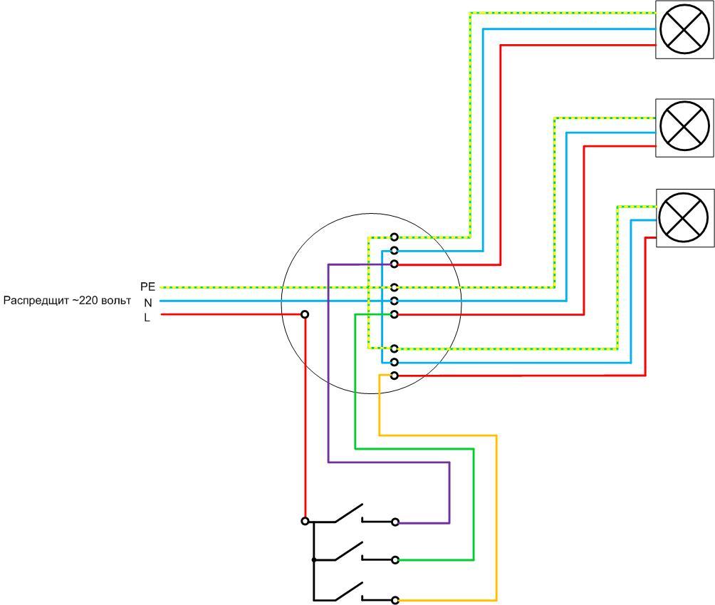
Similar circuit with a triple switch and three lamps looks much more complicated. More connections are made in the box, so you need to choose a larger junction box.
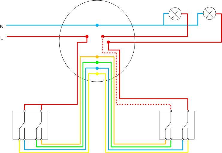
Even more difficult is the installation in a circuit box with two lamps and two double pass switches. Such a scheme is best done with a loop.
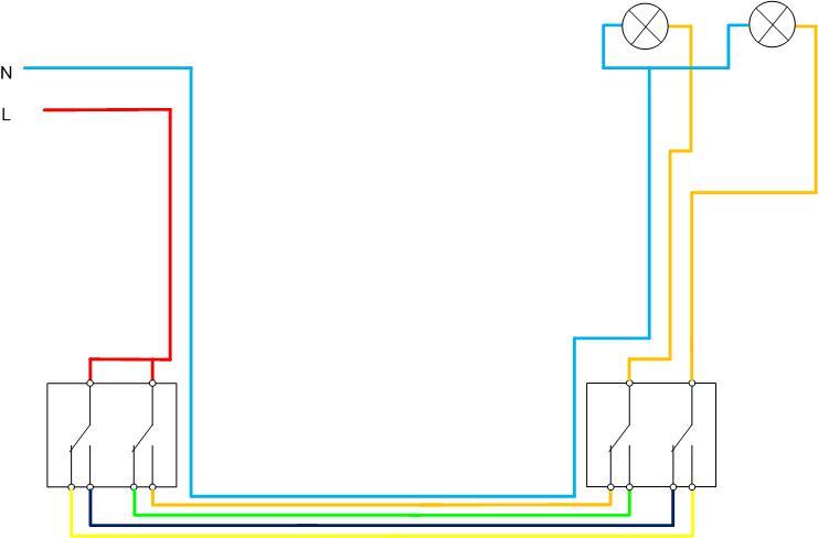
Obviously, in the second option, installation is simplified and the consumption of cable products is reduced.
Errors and possible malfunctions
One of the main mistakes when connecting the switch is the incorrect determination of the location of its terminals. Many people think that by default, a separately made terminal is always common. This is not true - manufacturers can arrange terminals in any order. Therefore, before starting installation, it is necessary to determine the conclusions of the device. This is easy to do if a circuit is applied to the device. If not, you can use a multimeter to test the internal connections. At the same time, this process will be a check of the device for serviceability.
Another common mistake is the incorrect connection of the conductors in the box. To minimize it, it is necessary to use cables with marked cores. If the cores are of the same color, after laying and cutting the cables, they must be called out with a multimeter and marked independently.
Video lesson: 5 mistakes when disconnecting junction boxes.
Security measures
The main safety measure when arranging wiring is all operations must be carried out under de-energized. If the lighting system is made from scratch, then connecting the power wire to the circuit breaker is done last. If work is being done to reconstruct or repair an existing circuit, technical measures must be taken:
- turn off the circuit breaker (or switch) of the lighting system;
- take measures to prevent spontaneous or erroneous switching on - disconnect the supply wire from the terminal of the machine;
- if the power supply system is made according to the TN-S principle, then the disconnected wire must be connected to the ground bus;
- check the absence of voltage on the phase wire.
Important! It is necessary to check the absence of voltage directly at the place of work - in the switch box or at the switch terminals.
Labor protection rules when working in electrical installations also prescribe the use of dielectric gloves, carpets, insulated power tools. It is unlikely that someone in everyday life will find protective equipment tested in the laboratory, but if possible they should be used. There is not much security. At least, you can visually monitor the condition of the insulation of a hand tool. With this approach, the probability of electric shock during operation will be minimal, the installation will be carried out accurately, quickly, will last a long time and reliably.