How to connect a two-gang pass-through switch - diagram
On sale there is a large number of household light switches of various designs and purposes. Many buyers have a question about the function, principle of operation and connection diagram of the so-called pass-through switches. The following describes the differences between such devices from conventional ones, as well as the use of such electrical appliances to control lighting.
Pass-through switch device and difference from other types
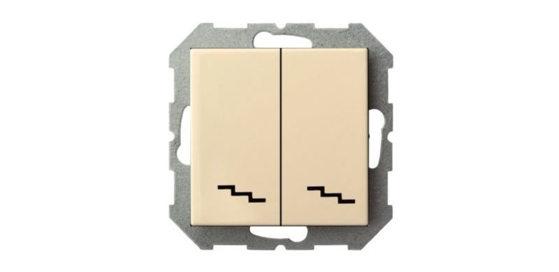
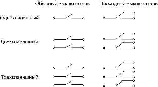
Externally, the pass switch does not differ from a household appliance designed to control light. It is equipped with one, two or three movable keys, each of which has two independent fixed positions. The fundamental difference from conventional switching devices is in the design of the contact group. If a standard device has one pair of contacts for closing-opening the circuit for each key, then for a pass-through switch, each movable panel controls a changeover contact group. In one of the positions one circuit is closed, in the other - another.In fact, such a device is a switch.
The 2-key switch has two contact groups that can be controlled independently. Three-key, respectively, three. To distinguish a pass-through device from a conventional one, it is often marked with arrows or a symbolic designation of a flight of stairs.
Important! Cross switches should not be confused with cross switches. Such switching devices also have a system of switching contacts. The difference between cross devices and two-button walk-through devices is that in the first one, two change-over contact groups are simultaneously controlled with one key. Another difference is in the internal circuitry. Normally open (normally open, NO) and normally closed (normally closed, NC) contacts of each pair of such a device are interconnected crosswise. Such devices are also used in lighting control circuits from three or more points.
According to the execution of the pass-through devices are:
- overhead (for open and hidden wiring);
- built-in (for concealed wiring).
There are also touch switches, but they are more expensive. In addition, most users agree that they are less convenient.
General connection diagram
Such a switch can be used to control the lighting load (lamps) - one, two or three, depending on the number of keys.
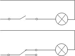
With this connection, one contact remains unused. But it is not economically feasible to use pass-through devices in this way - they cost a little more than standard ones.A common area of application for such devices is control circuits for lighting bulbs from different points.
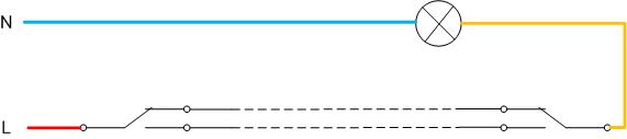
Such a connection allows each device to control the on and off of the light bulb, regardless of the state of the second. In practice, this principle can be applied, for example, when lighting in long tunnels and corridors. At the beginning of the passage, you can turn on the lighting, and after passing to the exit, you can turn it off. The next incoming person can again perform similar manipulations, regardless of the position of the switching devices and regardless of the direction of movement.
Where are the devices used?
Having two devices with two keys each, it is possible to organize independent control of two light bulbs from two points. Such a connection scheme for a two-button walk-through switch can be used, for example, in a warehouse with two zones or in a long corridor with a 90-degree turn, if it is impossible to illuminate both sections with one group of luminaires. Another option is large premises with a double lighting system (spot and general), as well as two-story houses.
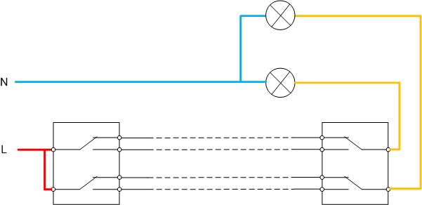
With such a connection, each lamp (or group of lamps) can be switched from two points independently.
Practical implementation of a scheme with two through devices
The specified scheme for connecting a double pass-through switch can be implemented in practice in various ways. The choice depends on local conditions and is made for reasons of ease of installation and economic reasons.
Connection via junction box
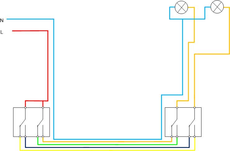
If the junction box to which the two-gang switch is to be connected is located approximately in the middle between the entrance and exit of the passage, the following wiring diagram can be applied:
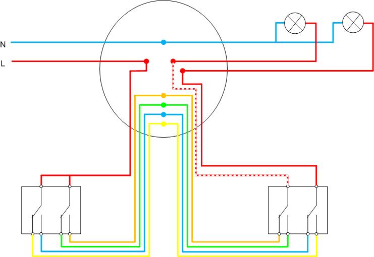
In this case, you need a cable:
- five-core for connecting the first switch;
- six-core for connecting a second switching device (its changeover contacts are connected separately and an additional conductor is required).
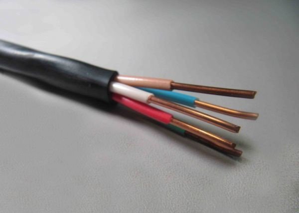
Cables are laid from the installation site of the switches to the junction box, where the cores are disconnected. It is obvious that the scheme turns out to be quite cumbersome, and when installation you must carefully monitor the correct connection. Significantly facilitate the work, minimize the likelihood of error and avoid the tedious and time-consuming part of the work on the continuity of the conductors will allow the use of cables with multi-colored core insulation or with numbering applied along the entire length of the conductors. To perform the installation correctly, you need to focus on the internal circuit of the device, applied on the back.
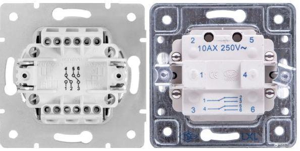
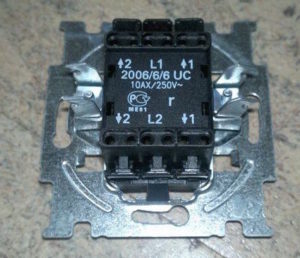
Another marking option is symbolic:
- L1 or L2 - changeover contacts for the first and second groups, respectively;
- arrow with a number indicates normally open and normally closed contacts.
To avoid mistakes, you can draw a sketch of the circuit on a piece of paper (using colored markers) or on a computer with the correct color coding. If the switch terminals are marked with symbols, they must also be marked on the sketch. This will prevent you from getting confused in the conclusions. The connected circuit can be marked in the figure.This will further reduce the chance of error.
This connection option involves many connections of conductors. It is difficult to lay such a number of wires and connectors in a standard junction box with a diameter of 60 mm. It is advisable to purchase a box of increased diameter.
Such a scheme is used in most cases in conjunction with hidden wiring. Its laying involves chasing the walls and arranging recesses for installing socket boxes for switches - devices with a hidden installation are usually selected.
Cable section is selected based on the load power. Many years of experience in arranging lighting systems allows us to say that copper cable section 1.5 sq. mm enough for almost any occasion. And the ubiquity of LED lighting does not give rise to an increase in this value. But in this case, another parameter is important. The length of electrical lines can be significant, and the voltage drop on the wiring can be significant. It is better to check for this parameter before starting installation. The easiest way to do this is with online calculators. If less than 95% of the input voltage reaches the consumers, the cross section must be increased by one step and checked for losses again.
Video lesson: Details about lighting control from 2 places.
Loop connection
In some cases, the connection diagram without a junction box may be optimal. This scheme will require the use of a cable with a maximum of five cores (or even four, if the neutral wire is not run in a common sheath, but along the shortest distance). It is more profitable from an economic point of view. Also in this version, installation is facilitated due to the use of a thinner cable - it takes up less space in the ducts and allows smaller bending radii.In this case, it is also highly recommended to use cable products with marked cores - this will greatly facilitate the work and reduce the likelihood of errors.
If such a topology of laying a neutral conductor is chosen, then a two-core cable is also needed to supply a supply voltage of 220 volts to the first switching device, and a three-core cable to connect two groups of lamps.
| Cable name | Number of cores | Section, sq. mm | Conductor material | Other properties |
| VVG 2x1.5 | 2 | 1,5 | copper | |
| VVGp - NG 2x1.5 | 2 | 1,5 | copper | Incombustible |
| VVGp - NG 3x1.5 | 3 | 1,5 | copper | Incombustible |
| VVGp - NG 5x1.5 | 5 | 1,5 | copper | Incombustible |
| NYM 5x1.5 | 5 | 1,5 | copper | Incombustible |
| VVG 6x1.5 | 6 | 1,5 | copper | |
| VVG-NG-LSx1.5 | 7 | 1,5 | copper | Non-flammable with low smoke generation |
The table shows some brands of domestic and imported cables that can be used when installing a lighting control system.
It is convenient to use a stub topology for open wiring with the installation of overhead devices. But there are no fundamental prohibitions on the arrangement of hidden wiring.
The video clearly demonstrates the installation of a two-gang switch.
A pass switch with two keys allows you to organize independent switching of two lamps from two or more (using additional elements) places. This provides not only convenience, but also significant energy savings by minimizing the lamp on time. Independent connection of such a system is easy.