How to repair a remote controlled chandelier
Recently, remote-controlled chandeliers have become popular. Their advantage is not only that the lamp can be controlled without getting up. Replacing a single-arm chandelier with a multi-arm one with the possibility of separate control of light-emitting elements according to the usual method leads to the need to replace the electrical wiring, open the decorative walls, etc. A chandelier with a remote control is easily connected to the place of a conventional lamp. Such a device can be bought assembled, or you can purchase a kit for self-embedding in a finished chandelier.
With all the advantages of such a solution, a lot of trouble for the owners is caused by the low reliability of such devices. But they can be repaired with a minimum set of tools and initial qualifications.
Chandelier schemes with remote control
Before talking about repairing a faulty remote-controlled chandelier, you need to find out how the system functions in the complex. This will help in diagnosing the problem and save time.
The general scheme for remote control of a chandelier is built on the same principle as the remote control of any consumer electronics with one difference - the lamp is controlled not by IR, but by radio. This is due to the fact that a conventional infrared communication channel can be blocked by interference from a nearby powerful light source.
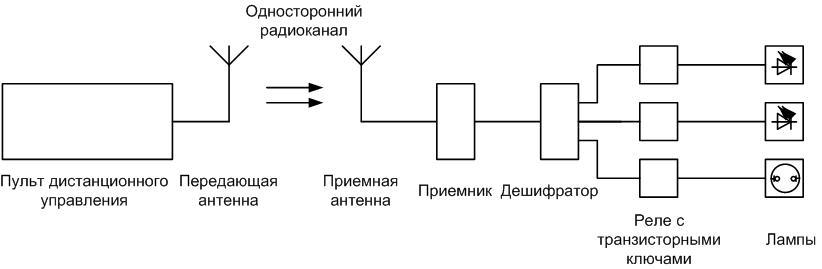
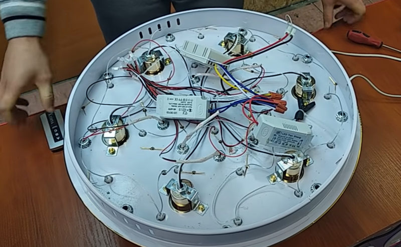
The transmitting part generates a command in the form of a sequence of pulses emitted by the antenna. On the side of the chandelier are the receiving part, consisting of:
- a receiving antenna in which the EMF is induced from the electromagnetic signal of the transmitter;
- the receiver itself, which converts the EMF into a sequence of electrical impulses;
- a decoder (decoder) of signals, which, according to the command, selects which lighting device to turn on or off.
The executive part is a transistor switches that control electromagnetic relays. The contacts of each relay include a lamp, which can be LED or made on the basis of an energy-saving lamp (both elements can be used in one chandelier). Incandescent lamps are not used in such lighting devices due to the high power consumption and the need to use relays with reinforced contacts.
The transmitter part looks like a consumer electronics remote control and is built on a similar principle.The only difference is that instead of an infrared LED, a transmitting antenna is installed.
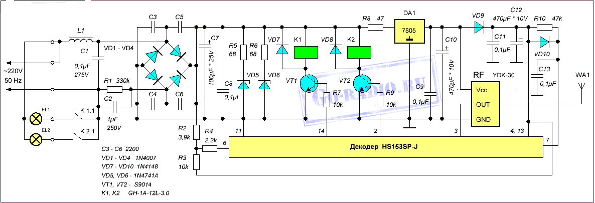
The work of the receiving and executive parts will be analyzed using the example of a typical chandelier circuit with two lamps. Other lighting devices are built on a similar principle.
The power supply circuit is built on a transformerless principle. Capacitor C2 dampens excess voltage. Next, a bridge-type rectifier with a smoothing capacitor is installed, so a constant voltage of 12 V is obtained to power the relay windings. To ensure a stable voltage of 5 V for the low-current part, an integral stabilizer DA1 is used. It powers the RF receiver and decoder.
The radio signal (RF) receiver is the YDK-30 module. It converts the EMF induced in the antenna into a sequence of pulses with an amplitude sufficient for the operation of the decoder. A decoder was built on the HS153 chip. Having received the command, the decoder turns on or off the corresponding transistor switch. This key, in turn, controls an electromagnetic relay that supplies voltage to the corresponding lamp. Luminaires are built on LED or halogen lamp with the appropriate driver or electronic control gear.
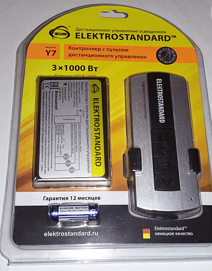
Important! Almost all circuits of the receiving and actuating part of the Chinese-made remote control system (even with assurances on the packaging that the device was developed in Germany) have a transformerless power supply circuit with quenching resistors or capacitors. When repairing or checking the circuit, it must be borne in mind that all elements are under full voltage of 220 V. Failure to comply with labor protection requirements can lead to electric shock.
Chandelier malfunctions with remote control
Before you start repairing a chandelier with a remote control, you need to conduct a thorough diagnosis and determine the faulty element. Repairing a lamp with a "scientific poke method" is not a good idea. This can lead to unjustified financial and time costs.
Chandelier won't turn on with remote
If the chandelier does not respond to pressing the remote control buttons, then the first thing to check in this case is whether the batteries are alive. You can measure the voltage on them, you can immediately replace the galvanic cells.
Then there are two options:
- remote control is defective;
- receiver is faulty.
In the first case, you need to try to find the remote control from such a chandelier and try to control it. If everything is in order, repair the remote control. If not ... It will be possible to unambiguously establish the operability of the transmitting part only if its operating frequencies are known and there is a radio receiver for these frequencies. It's easier to find another remote or rely on intuition.
If intuition suggests that the malfunction is on the side of the chandelier, the test must begin with the presence of power. The probability of failure of all transistor switches and relays at the same time is extremely small, but individual elements in the power circuit may fail. It is necessary to check the voltage on the smoothing capacitor after the diode bridge. If it is very different from 12-15 V, then it is necessary to diagnose and repair the rectifier. If everything is in order, check the voltage at the output of the integral stabilizer - in this case +5 V. Take measurements carefully, remembering that all radio elements are energized at 220 V.
If voltage is present, you need to make sure that there are pulses that appear at the output of the receiver when you press the buttons on the remote control. You can do this with an oscilloscope.If not, you can try to make a simple LED probe.
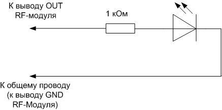
If you're lucky to see LED flashes, then the RF receiver is working.
Important! Before checking circuits with an oscilloscope, you must make sure that its input is rated for a voltage of at least 310 V (peak-to-peak mains voltage). Otherwise, any connection error may damage the device.
If there are pulses at the output of the RF module (at the input of the decoder), it is necessary to check the response of the decoder to commands. When signals are given by the remote control, the unit levels should appear and disappear at the outputs that control the transistor switches. You can check this with a multimeter in voltmeter mode or with the same probe.
Video lesson: Diagnosis of circuits and repair of an LED chandelier with a control panel.
Chandelier clicks but won't turn on
If relay clicks are heard when issuing commands via the remote control, this means that the following are working:
- transmitting part;
- power supply circuit of the receiving and executive parts;
- decoder;
- transistor switches and relay windings.
And the light-emitting elements (their electronic circuits) may be faulty or the relay contacts are burnt (burned out). Since the simultaneous failure of all lamps is unlikely, the cause must be sought in the contact group - here simultaneous burning looks more real. The reason for this may be a discrepancy between the operating current of the relay contacts and the current consumption of the lamps. Over time, this leads to a loss of conductivity.
If the design of the relay allows disassembly, you can try to clean the contacts. If not, you need to change the relay.
You can change the element to the same type, but it doesn’t make much sense - after some time, the contacts will fail again.We must try to pick up a more powerful relay, as far as space and installation dimensions allow. Some types of relays and the current switched at 220 V AC are summarized in the table.
| relay type | HRS-4H | SRD-12VDC | SRA-12VDC | JS-1 |
| Switched current, A | 5 | 10 | 20 | 10 |
Important! Using automotive relays to replace standard or homemade designs is not a good idea. Their windings consume too much current, and the contacts are not designed for switching voltage of 220 V.
Also, in some cases, there is a violation of the soldering of the relay contacts due to constant heating. Before replacing, you must carefully examine the sites to which the contacts are soldered, and try them solder. Sometimes it helps.
Feature video:LEDs
Incorrect operation from the remote control
It happens that some of the lamps are controlled from the remote control, some do not respond to button presses. The reason may be the physical wear of the buttons. The radical way is to replace the remote control. You can search in stores or on marketplaces on the Internet for repair kits for repairing remotes. There are also spare contacts for buttons.
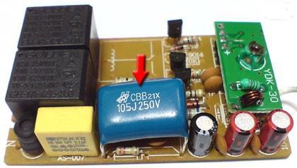
Also on specialized forums there is information about the incorrect operation of the chandelier due to the poor quality of the film capacitor in the power circuit. At the same time, channel 1 continues to work, 2 and 3 do not. It is easy to fix - you need to replace the container.
LEDs and bulbs do not light up
If everything works, but individual LED or halogen bulbs have ceased to glow, then the reason must be sought in them or in the drivers (electronic gear).
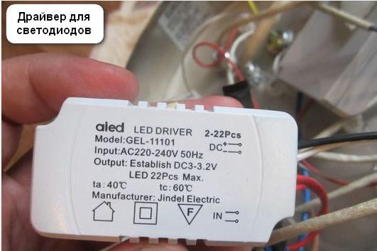
It happens that one element burns out in a chain of LEDs.You can find it with a call and replace it. Or just close in the hope that the driver will pull it out. You should not rely too much on this method, because in many fixtures, in order to save space and reduce cost, instead of a full-fledged driver, they put damping resistor. But to diagnose repair such a "driver" easily. Just check the resistance with a multimeter. If a full-fledged current stabilizer is used in the LED lamp, then its repair will require the availability of instruments and qualifications.
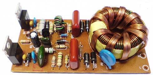
performance halogen bulbs can be tested by substituting with known good parts. The electronic transformer that powers the lighting element can be replaced or repaired.

You can check in a row all semiconductor elements (transistors, diodes). Winding elements in case of failure, as a rule, will have traces of burning. To find the malfunction of the remaining parts, you will have to work with the devices. First of all, localize the fault by checking the presence of a constant voltage of 220 V at the output of the bridge. Next, use an oscilloscope to check for fluctuations at the output of the pulse transformer and, using the information obtained, find the faulty element.
Other malfunctions
During the operation of the chandeliers, other malfunctions may occur. The description of all possible options is endless and beyond the scope of the review. Therefore, in each case, you will have to look for them yourself. This is not always easy, you will need to turn on your quick wit, read the technical literature. But this is the only way to improve skills.
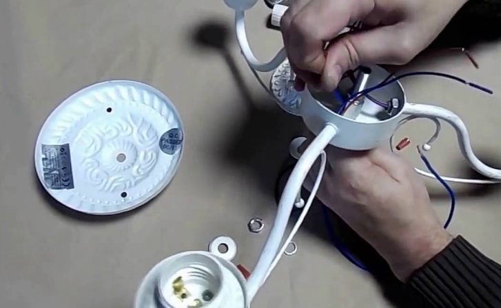
Do-it-yourself chandelier repair with a remote control
After a well-executed diagnosis, the repair will be easy.It comes down to replacing the identified defective element. You can buy these components in electronic component stores or online.
Replacing the chandelier control unit
If the diagnostics of the controller did not give clear results and the owner believes that it is irrational to purchase a new set of transceiver parts, you can convert the chandelier to local control from a two-key light switch. It is advisable to carry out this alteration if the lamp with remote control is installed in place of the chandelier, which was previously switched, and the corresponding wiring is already available. Otherwise, you will have to carry out an additional wire, and this is the opening of the decorative cladding of walls and ceilings, chasing, etc.
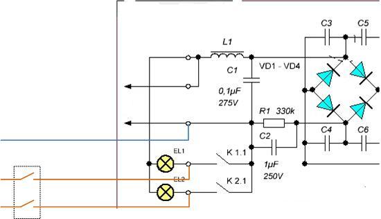
If the wiring is already ready, then you can connect the luminaire without interfering with the internal circuit using the existing terminal block for external connections. The advantage of this option is that if the owner decides to replace the controller in the future, reconnection will be minimal.
Experience shows that if a chandelier controlled by a remote control fails, it is quite possible to give it a second life. You will need a small set of tools, basic knowledge of electrical engineering and the desire to think.