How to connect a single-gang switch
There are switches on sale, in the technical documentation for which the name "pass-through" is indicated. What is their peculiarity, how they differ from the usual ones, what is the scope of their application - all this below.
Sometimes when controlling lighting, you need to turn on or off the light from two or more places. This situation can occur in rooms without constant presence of people - long passages or large areas with two or more exits. Turn on the light when you enter the corridor, turn it off when you leave. For this purpose, pass-through switches have been developed and are being produced - such a circuit is easily built on them. Another example - staircase lighting (marches).Entering the house you need to turn on the light, having risen to the desired floor - turn it off. Therefore, such devices are also called marching (and also duplicating or flip).
In residential areas, such devices can be used in large rooms with several entrances, as well as in bedrooms. When entering the bedroom, you can turn on the light, and turn off the device next to the bed. The lighting of children's rooms is built on the same principle for one or more children - one switch at the entrance, the rest - near the sleeping place of each child.

Advantages and disadvantages
The advantages of the pass-through apparatus are manifested when it is used in the area intended for it. With it, you can create lighting control schemes that cannot be built on conventional devices. The disadvantages include only the impossibility of determining the state of the lamps by the position of the key. And this minus cannot be bypassed..
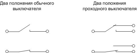
The principle of operation and the difference from a conventional switch
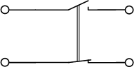
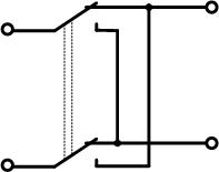
The pass-through switch differs from a conventional switching device only in the presence of a specific contact group - with changeover contacts. If a conventional switch can only close or open an electrical circuit, then a pass-through switch can alternately connect to one or the other line. Therefore, it is actually a switch.
Marching devices are available for sale in single-key and two-key versions. In the first case, the circuit of the through switch is standard - one key controls one contact group. In the second, two keys independently control each of their contact system.That is, two devices are placed in one housing, not connected to each other either electrically or mechanically.
When studying the operation of a changeover contact system, the conclusion suggests itself that the through switch can be used as a conventional one - by using only two contacts (one movable and one fixed). To do this, you need to connect to only two terminals. This inclusion can be used if there is no conventional switch at hand. But it is irrational to specifically install a changeover device instead of a standard one - its cost is higher.
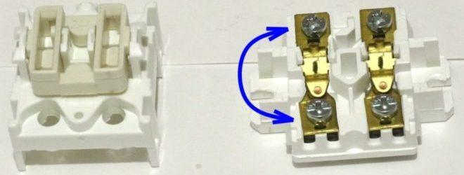
It may be necessary to make a passage device yourself. The easiest option is to replace it with a two-gang switch.
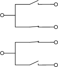
It can be seen from the diagram that it is easy to organize a changeover contact group from such an apparatus. But there is a significant drawback: you need to manipulate two keys, and you will have to set them in the opposite position to each other. This is inconvenient and can lead to confusion. Simultaneous switching on or off will not lead to an accident - the contacts will simply duplicate each other. But this will not bring the desired effect.
For some two-key devices, two contact groups are not combined.
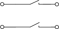
In this option, you can try to turn one of the contact pairs 180 degrees (if the design of the switch allows it). After that, it remains only to connect the keys mechanically so that the contacts can be manipulated at the same time (for example, by means of glue). Get a full-fledged switch.
It is possible to build a transitional home-made switch from a conventional two-keyboardist with combined inputs, but this will require a serious alteration of the contact group - trimming, rearranging, etc. It is easier to buy a standard device or use a switch for production use (a button with a position lock or a toggle switch), sacrificing aesthetics.
Recommended reading: The device and principle of operation of the pass-through switch
Wiring diagrams
Control circuits for lighting devices are assembled on walk-through devices so that the light can be turned on or off from two or more points with one manipulation, regardless of the position of other switching elements.
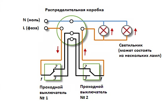
Turning on the light from two places
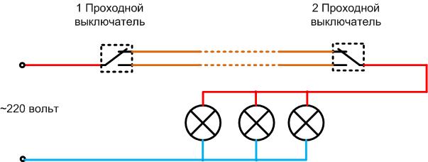
To build an on-off circuit for fixtures from two points, you will need two switches with changeover contacts. It can be seen from the diagram that no matter what position the first element is in, the second one can close and open the lamp supply circuit.
If apply double switch, you can control two luminaires or groups of luminaires. For example, spot or general room lighting. Or, instead of the second lamp, you can connect another consumer (forced ventilation system, etc.).
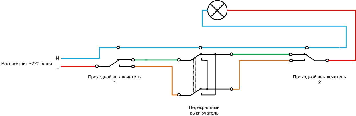
Three-point luminaire control
In order to independently turn on lamps from three points, in addition to cross-over devices, you will also need a cross one. Its key controls a contact group containing two changeover pairs connected in a special way:
- each pair has its own separate entrance;
- the normally open contact of one pair is connected to the normally closed contact of the other pair and connected to a common terminal;
- the normally closed contact of one pair is connected to the normally open contact of the other pair and connected to the other common terminal.
Such a device is also called reversible - with its help you can change the polarity of the DC voltage on the load, and reverse the direction of rotation, for example, of a DC motor.
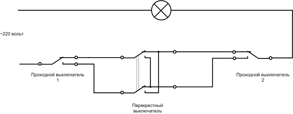
Such a scheme for connecting walk-through and cross switches is useful in T-shaped aisles or in children's rooms for two.
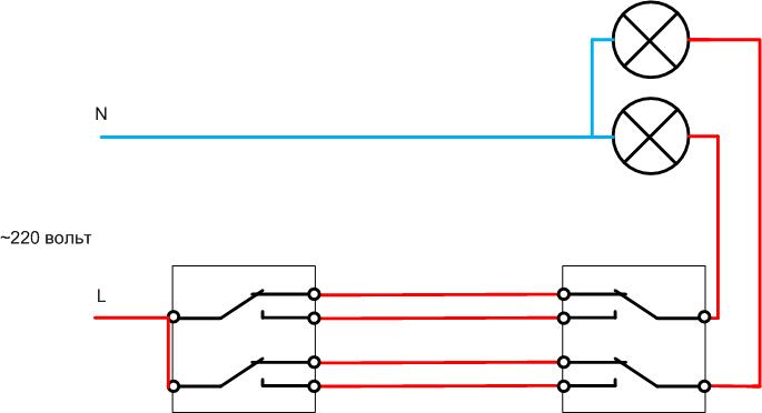
Four-point luminaire control
By adding one intermediate reversing apparatus, the light can be controlled from four different locations.
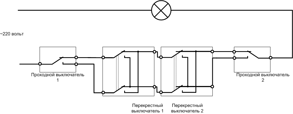
The circuit seems cumbersome due to the abundance of contacts. But in fact, the switches are connected to each other by cables of only two cores.
Independent light control from five places
By the same principle, you can increase the number of points for switching on and off lighting fixtures up to five.
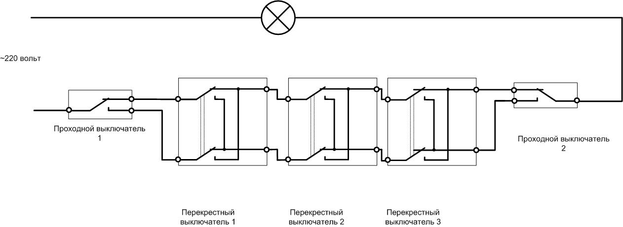
The addition of each intermediate reverse element increases the number of control points by one. Theoretically, the number of lamp switching points can be increased to infinity, only a sufficient number of cross switches are required. In practice, even five controls are rarely needed.
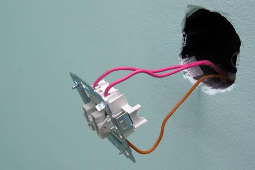
How the switch is mounted
Installation of a mid-flight electric light switch of fundamental differences from installation of a conventional switching element does not have. Similarly, you will need:
- select the type of wiring (open or hidden);
- to outline cable laying routes;
- prepare channels (for open wiring) or install support insulators (trays) for open wiring;
- equip the installation sites of distribution boxes and switching devices, mount lamps;
- lay and fix the cables, bring the ends to the sockets and distribution boxes (when they are installed);
- cut the ends of the conductors;
- carry out the disconnection in junction boxes and connect the corresponding cable cores to the switch terminals.
Important! The rules for the installation of electrical installations require that the distance from the installation site of the switches to the gas pipes is at least 50 cm. Otherwise, the PUE contains only advisory information.
After that, you can check the installation, apply voltage and test the operation of the lighting system.
Choosing a cable for lighting
The cross section of the cable for the arrangement of electrical networks is selected according to the economic current density and is checked for thermal and dynamic resistance to short-circuit currents. For the implementation of lighting networks in all respects, copper products with a cross section of conductors are suitable 1.5 sq.mm. This has become a kind of standard for laying lighting wiring. A smaller cross section, even if it meets the local selection criteria, does not provide mechanical strength. More leads to irrational spending of finances.
Although in Russia wiring with cables with aluminum conductors is allowed, it is strongly recommended to use only products with copper conductors. Also, you can not use conductor products with stranded wires.
For wiring arrangement, depending on the selected circuit and topology, cables with a number of cores from 2 to 4 may be required.Common types of cable products suitable for work are shown in the table.
| cable type | Section, sq. mm | Material | Number of cores | Additional properties |
|---|---|---|---|---|
| VVG-Png(A) 2x1.5 | 1,5 | copper | 2 | Flat, non-flammable |
| VVG-NG(A) 2x1.5 | 2 | Incombustible | ||
| NYY-J 2*1.5 | 2 | Non-flammable, low smoke | ||
| VVGP- 3x1.5 | 3 | Flat | ||
| VVG-NG- 3x1.5 | 3 | Incombustible | ||
| CYKY 3x1.5 | 3 | Incombustible | ||
| VVG-NG- 4x1.5 | 4 | Incombustible | ||
| NYY-O 4x1.5 | 4 | Incombustible |
Read more in a separate article: Which wire to choose for lighting wiring
Installation using a junction box
To install a lighting system using marching vehicles, you can use a junction box. This choice has the following advantages:
- disconnection takes place in one place;
- you can easily check the correctness of the installation by dialing;
- in some cases, the cable is saved;
- the installation is orderly, it is easy to understand even for those who did not directly connect.
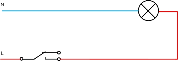
Connection schemes are different, but the installation principles remain unchanged:
- from the switchboard comes a power cable with a phase, zero and protective core (L, N, PE respectively);
- conductors N and PE go in transit to consumers (if there is more than one load, they diverge into the corresponding number of branches);
- the phase conductor breaks, the cable goes down to the switches, then it branches and goes to consumers.
As an example, the installation of a control circuit from three places is shown (for a two-wire network, without a PE conductor). The disadvantages of this method are obvious:
- from the last switch according to the circuit, it is necessary to pull the cable back to the junction box, this is irrational, since its length can be significant;
- a separate cable must be laid on the lamp, this is not always optimal.
Another disadvantage of using junction boxes is manifested parallel complication of the scheme.
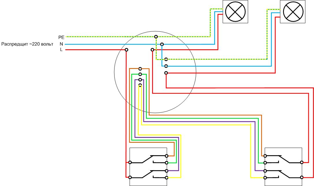
As an illustration, a diagram with two marching and one reversing switches is shown. The more complex the scheme, the more:
- with a large number of cores, cables are required;
- more connections occur in the box, which increases the likelihood of installation errors and requires the use of larger junction boxes.
Therefore, if possible, use cable routing. Although the decision on the topology of cable routes must be made each time individually, taking into account local conditions.
Safety measures for the operation of lighting networks
At designing and installation of lighting, it should be remembered that the lighting system must be connected through a separate circuit breaker, which is mounted in the switchboard. For wiring with a core cross section of 1.5 sq. mm. a 10 A machine is installed.
Another point of safety is the grounding of lighting fixtures. Mandatory if there is a PE conductor. It is connected to the luminaire terminal marked with the letters PE or the earth symbol.
Possible connection errors
The main mistake when installing such switching devices is incorrect definition of switch pins. Intuitively, a terminal located on the opposite side of the other two is considered a common contact. This is far from always true. Different manufacturers can arrange the contact system in any way. Therefore, you need to look at the markings, and even better - ring out the location of the contacts using a multimeter.
The remaining possible errors are reduced to incorrect installation. To minimize the likelihood of incorrect connection, it is recommended to use cable products with marked cores (color or numbers).
Video tutorials: Schemes and errors of connecting switches.
The use of mid-flight switches provides ample opportunities for creating lighting control systems. But their use must be conscious. And you need to start by building a diagram on paper. This makes it easier to find errors and cheaper to fix them. And only after reconciliation of the scheme, you can begin to prepare for installation. Then success is guaranteed.