How to make a power supply from an energy-saving lamp
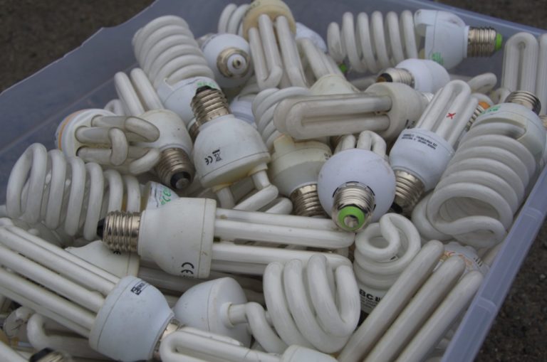
Energy-saving lamps are complex devices whose elements can be used in radio engineering to create new devices. In particular, it is possible to make a power supply unit from an electronic ballast of an energy-saving lamp.
The device and principle of operation of the electronic ballast
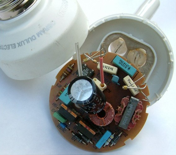
Electronic ballast (electronic ballast) is an important component of an energy-saving lamp, responsible for activating the contacts and maintaining a stable glow without pulsations.
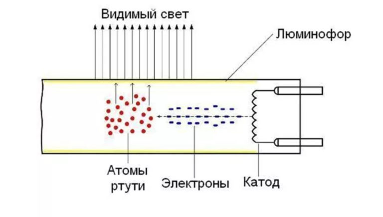
The electronic ballast is present in almost all fluorescent lamps that create light by heating inert gases or mercury vapor in a closed volume.
Electronic ballast consists of elements:
- filter for cutting off interference from the mains;
- rectifier;
- power adjustment device;
- smoothing filter at the output;
- additional load (ballast);
- inverter.
In order to save money, manufacturers can strengthen some elements and get rid of others.This affects the difference in the parameters of electronic ballasts on the market.
The ballast is powered by current from the mains and creates a constant voltage supplied to the lamp contacts. The circuit is a switching power supply or driver that can be converted into a full-fledged PSU for use in other electrical circuits.
DIY PSU
Creating a UPS from energy-saving lamps includes a preparatory stage and a conversion process. It is important to perform all actions in compliance with safety regulations when working with electrical appliances.
Preparation of tools and materials
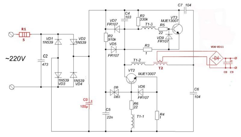
The diagram of a standard energy-saving lamp is shown in the figure below. Red elements are needed to start the lamp and will not be required when assembling the power supply.
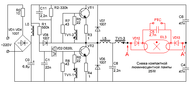
The circuit resembles a switching power supply. The differences concern only the built-in choke. It must be replaced with a transformer by one of the methods:
- winding on the existing choke of the secondary winding with the appropriate parameters;
- complete removal of the inductor and installation in its place of a transformer suitable for performance indicators from another electrical appliance.
When developing an energy-saving lamp, manufacturers pay special attention to the compactness of the device. All elements are selected so as not to take up much space. For this reason, there is no talk of a power reserve. It is advisable to create a power supply within the initial power of the lighting device. This ensures the durability of the circuit and protects against overheating.
Scheme for converting electronic ballasts into UPS
The conversion of the electronic ballast into a power supply contains:
- Creating a galvanic isolation for the safety of the circuit.
- Lowering the output voltage.
- Rectification of the output voltage.
To create a PSU with a power of up to 15 W, you will need a winding wire (about 10 cm), a set of diodes (4 pieces), two capacitors and an electronic ballast from a 40 W lamp.
The modified scheme looks like.

Throttle performs the functions of an isolation and step-down transformer, a set of diodes rectifies the alternating voltage. The capacitors in the circuit smooth out the pulses and provide stable performance for the power supplied to the appliance.
Rework procedure:
- The bulb and the capacitor next to it are removed from the original circuit.
- All lamp leads are interconnected, closing the capacitors and the inductor that previously went to the light bulb.
- In this case, the inductor becomes the main load of the circuit. It remains to wind the secondary winding on it with a wire with a diameter of not more than 0.8 mm. A few turns are enough.
To determine the exact number of secondary turns, use the following technique:
- On the throttle 10 turns are wound, after which the diode bridge is connected.
- The circuit is loaded with a 30 W resistor with a resistance of about 5 ohms.
- Using a multimeter, measure the voltage across the resistor.
- The resulting voltage is divided by 10 (the number of turns), thereby obtaining the voltage from one turn.
- The required voltage is divided by the calculated indicator. This is the desired number of turns of the secondary winding.
Any diodes designed for a reverse voltage above 25 V and a current of 1 A can be used in the circuit.
The disadvantage of this scheme is the instability of the output voltage.You can solve the problem by installing an additional stabilizer for 12 volts.

Is it possible to increase the power
The power of the power supply created from electronic ballasts usually does not exceed 40 W, which may not be enough. In addition, the choke installed in the circuit introduces additional restrictions. The system simply cannot reach maximum power, and even a figure of 40 watts is observed infrequently. An increase in current does not give the desired effect, since the magnetic circuit begins to operate in saturation mode, reducing the efficiency of the circuit.
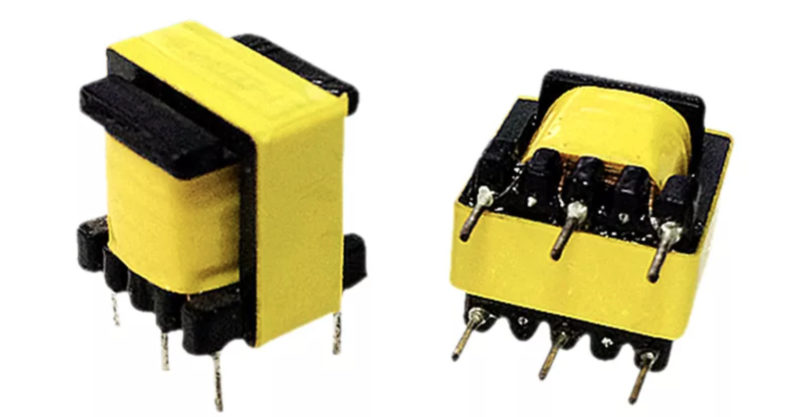
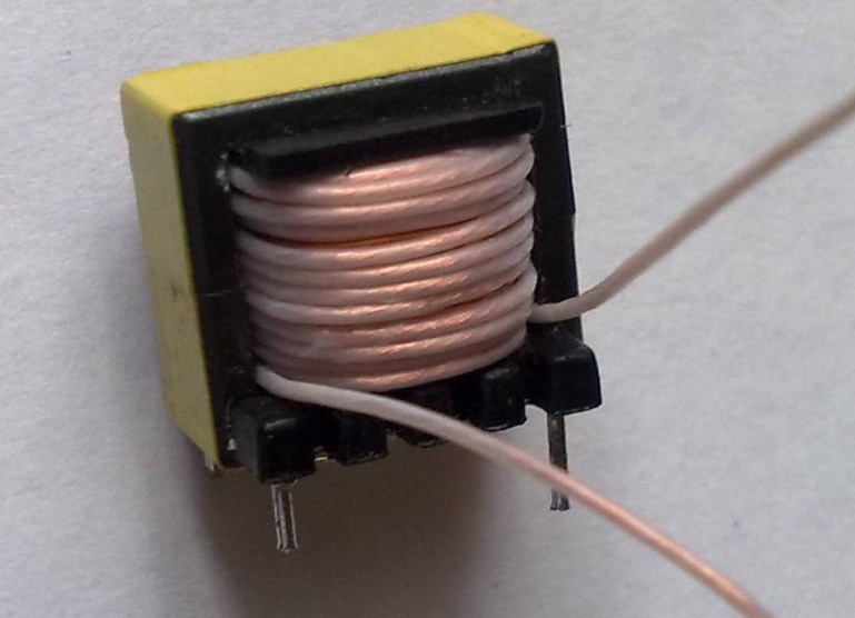
To increase the power of the PSU, it is enough to connect a pulse transformer instead of a standard inductor. The process is more complicated than reworking an energy-saving lamp, but you can still do it yourself if you have knowledge in the field of radio engineering.
The transformer can be obtained from a computer power supply or other equipment. Additionally, a 5 ohm resistor with a power of 3 W and a high-voltage capacitor with a capacity of about 100 microfarads with an operating voltage of 350 V are required.
The connection diagram is shown below.
The pulse transformer is installed in place of the inductor. The primary winding is connected to the converter, the secondary is a step-down. Increasing the power of the resistor and the capacitance of the capacitor completes the change in the standard power supply circuit based on electronic ballasts.
Now it is possible to give a current of 8 A at a voltage of 12 V. This means that the PSU can be used in screwdrivers or household appliances with similar requirements.
How to avoid mistakes
To avoid problems with the electronic ballast power supply, follow the recommendations:
- The first start-up of the power supply is best done by connecting to the network through a 60-100 W incandescent lamp. The lamp will become an indicator of the correctness of the circuit. If the device shines weakly, then the PSU is assembled correctly. A bright light indicates an error that will quickly disable the transistors.
- Before starting the power supply, test it through a load resistor. It is important to monitor the temperature of the circuit components. The transformer and transistors should not heat up above 60 degrees.
- Strong overheating of the transformer requires an increase in the cross section of the winding.
- Overheating transistors need to be equipped with compact radiators that effectively remove heat.
- It is better not to use a power supply unit created from an energy-saving lamp with expensive electrical appliances and gadgets. Voltage instability and the possibility of breakdown make this risky.
Related video: 6 homemade products based on an energy-saving lamp.
Six simple homemade products based on an energy-saving lamp with your own hands.
