The device and connection diagram of the pass-through dimmer
The market of household electrical appliances provides consumers with a wide choice of equipment that allows them to equip the lighting system for comfortable use, as well as with the ability to save on electricity bills. New products are constantly offered for sale, and it is not easy to immediately understand the application of which, without being a professional. The subject of the review is a device that combines the capabilities of a dimmer with the functions of a pass-through switch. It's called a pass-through dimmer.
What is a pass-through dimmer
In some cases, it becomes necessary to turn on and off the lighting from two or more points independently. The scheme for such a case is known, for 2 places it is implemented on two pass switches. If more is needed, the required number of cross switches is added.
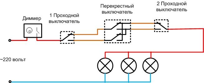
If necessary, smoothly adjust the level of illumination, such a scheme is easy to supplement dimmer - a device for smooth regulation of the level of illumination. The dimmer must be connected to a break in the phase wire, and it does not matter which side - before the first pass-through switch or after the second one.
Dimmers are usually equipped with power switches, so they can be assigned the functions of the main control. From the remote control, you can not only adjust the brightness, but also turn off the voltage of the lighting network, regardless of the position of the other switches (unfortunately, you won’t be able to turn it on independently). The disadvantage of such a scheme is the need to install an additional device, the associated arrangement of the socket box, and the search for this free space.
Therefore, it is often more profitable to use a combined device - a dimmer + a pass-through switch.
It combines the functions of two devices:
- allows you to adjust the brightness of the lighting;
- has a changeover contact group, which allows using the device as a pass-through switch.
Therefore, when using it, certain savings are achieved, but control function from the central console is lost.
Advantages and disadvantages of a pass-through device
Equipping the dimmer with a special contact group does not fundamentally change its properties, so the pass-through dimmer has all the pros and cons, which is normal. Its main advantages:
- the possibility of saving electricity;
- extending the life of incandescent lamps due to the smooth heating of the filament.
The main disadvantage is the occurrence of a strobe effect in some modes, which does not allow visually adequately assessing the state of rotating mechanisms.
The principle of operation and the device of the regulator
Dimmers come in various designs, and the most popular is swivel.But in a control circuit with two pass-through switches, such a dimmer is unsuitable - it switches only in the minimum brightness position. Therefore, to organize such a control scheme, other types of dimmer drive are used:
- rotary-push (switches in any position of brightness);
- controlled remotely (using a remote control);
- push-button (with "more-less" buttons and a separate key for switching);
- touch, as well as other types of dimmers.
They have one basic principle - brightness control and contact management are performed independently.
The internal block diagram of the dimmer looks like this:
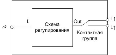
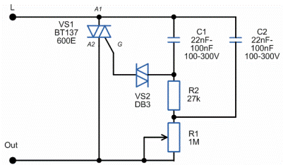
The control circuit is usually built on a trinistor or triac. The average current is changed by cutting off part of the half-cycle of the alternating voltage.
If the dimmer is built according to a similar scheme, it does not matter which side to put the dimmer on - from the supply side or from the load side. It does not affect the operation of the circuit. For other schemes, this moment must be studied individually.
But it makes no sense to install regulators on both sides at once: they will try to “cut” the sinusoid on their own, the brightness will be adjusted unpredictably. With such a scheme, one of the devices can only be used for switching, permanently setting it to the maximum brightness position. But from an economic point of view, this is not true - cheaper to buy a switch with changeover contacts.
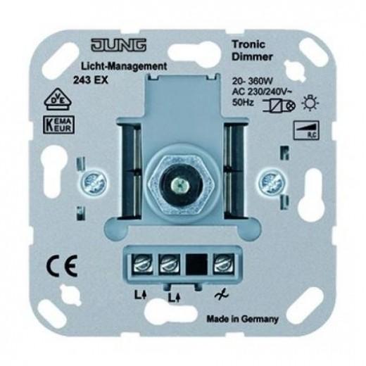
The outputs of the device are connected to external terminals marked with the purpose.
Important! Letter marking of characters to a single standard is not given.Manufacturers may apply other designations of external terminals. In many cases, a stylized diagram is applied to the switch instead of symbols.
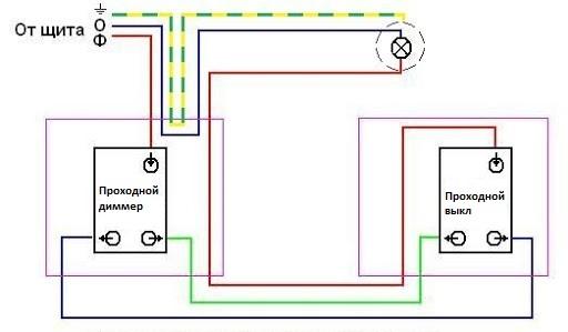
It is almost impossible to find a cross dimmer on sale. If someone produces such devices, then the circuit will turn out to be cumbersome, unreliable. After all, the brightness must be adjusted simultaneously on two channels at once. Therefore, the optimal scheme would be one that uses one pass-through dimmer, one pass switch and the required number of cross switches.
Materials and tools for installation
If the wiring and installation locations of the switching devices have already been completed, then a minimum list of tools is required:
- fitter's knife (you can use it to remove insulation);
- a set of screwdrivers (for partial disassembly, assembly and mounting of devices);
- wire cutters (for shortening conductors);
- an indicator screwdriver and (or) a multimeter (for monitoring the absence of voltage and checking the correct installation).
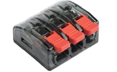
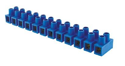
If the wiring is carried out with a copper cable (it is recommended to do just that) and installation is to be done in a junction box by twisting, then the joints must be soldered. To do this, you need a 40-60 watt soldering iron with a set of consumables. To isolate the twists, you will need electrical tape or caps. If you choose to mount with terminals (screw and spring), then you need to purchase a set of terminals.
If there is no wiring, additional tools will be needed to arrange it. Their set depends on the intended laying method. For open wiring, you will need trays, brackets or racks and a drill (perforator) for installation.For a closed one - a tool for making strobes (a strobe cutter, a puncher, in extreme cases, a chisel with a hammer) and a drill with a crown for making recesses.
Wiring diagrams
A dimmer with a changeover group of contacts is connected in the same way as a conventional pass-through switch, regardless of the type of impact on the contact group. Two options are possible.
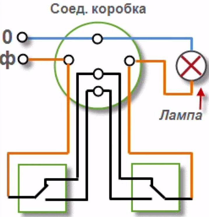
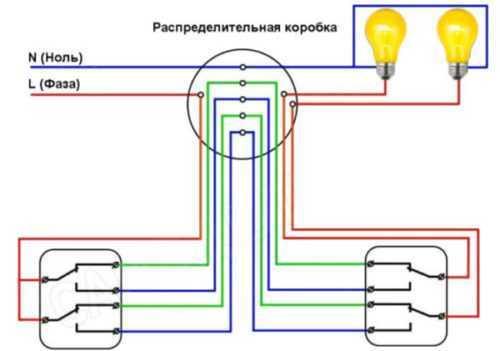
Using junction box
It is possible to mount a pass-through dimmer using the classic method - using a junction box. Such installation looks more professional, in the box, if necessary, it is easy to make switching or partial wiring diagnostics by ringing individual conductors.
But in this case, a large number of connections must be assembled in one box, this complicates installation, increases the likelihood of errors. These shortcomings are only exacerbated by the complexity of the circuit - the addition of cross switches or the use of two-key pass-through devices.
Train
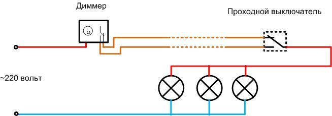
From the previous drawings, it is obvious that the conductors connecting the feed-through and crossover switching devices do not have to be brought into the box. They can be laid over the shortest distance. Such a connection scheme for a pass-through dimmer allows you to mount a lighting system without a junction box. Elements are connected successively - train.
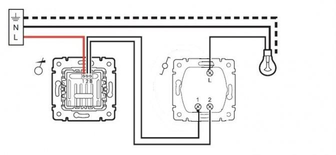
The N and PE conductors can be run directly on the lamp, or they can be laid in transit along with the phase conductor.In any case, the phase conductor is connected to the first pass-through device, connected by a loop to the second one, then the supply wire goes to the lighting device.
With such a gasket, there are no problems inherent in installation using a junction box. Another important advantage is when laying a feed-through circuit with a loop significant savings on cable products.
Recommended for viewing.
Important points when choosing
Unlike a conventional walk-through switch, a dimmer with a changeover contact group may not work with all types of lighting fixtures. This is due to the peculiarities of the principle of operation of lamps. Before installing (and even better - before purchasing) a dimmer, you need to find out for which area the device is used. This can be done by marking the device or by studying the technical data sheet.
| Letter designation | Symbol designation | Type of load | Permissible load type |
|---|---|---|---|
| R | Active (ohmic) | Incandescent lamps | |
| L | inductive | Voltage transformers for low voltage lamps | |
| C | capacitive | Electronic transformers (voltage converters) |
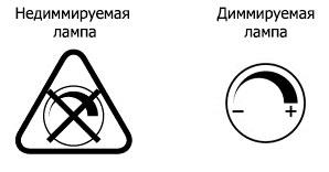
There are also universal devices, their marking contains several letters (for example, RL). There are also universal models, they can be connected to the network with any kind of lamps, including LEDs. But the lamps themselves must be labeled Dimmable or the corresponding icon.
The connection diagram of a pass-through dimmer has no fundamental differences from the connection diagram of a conventional pass-through switch. But the nuances still exist, before developing a lighting system, it is better to study them.With a conscious approach to organizing a network, it will last a long time and will only deliver a feeling of comfort. If this is not done, you can suffer unforeseen losses of money and time.