Connection diagrams for dimmers with and instead of a switch
The question of regulating the brightness of lamps arose, probably, immediately after the invention of electric lighting devices. The simplest and most obvious way is to include in series with lamp resistors - was soon recognized as a dead end. With this method, part of the power is uselessly dissipated by the resistance, and the main goal of the adjustment is not achieved - saving electricity. Ways were found to reduce the brightness of the glow by distributing power over time using electronic keys. Based on this principle, household appliances have been developed and used, called dimmers (to dim - muffle, make dim).
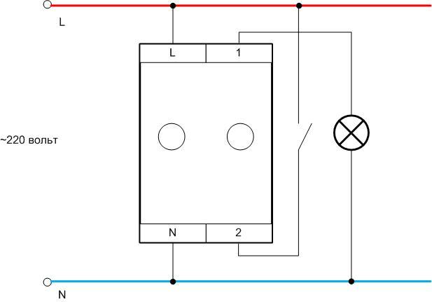
Simple dimmer
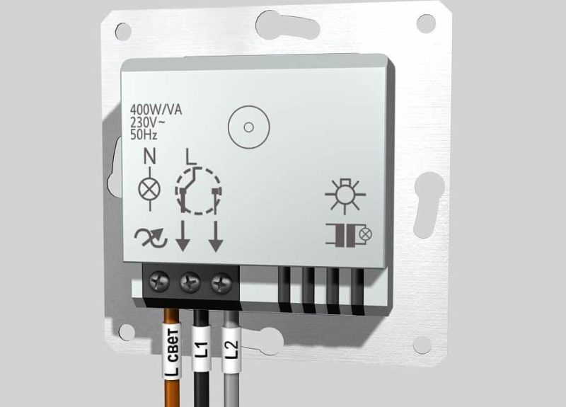
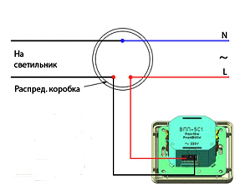
In the most trivial case, the dimmer connection diagram is simple: break the phase wire of a chandelier or other lighting fixture, like a switch. It performs the functions of a switch - in addition to the service of lighting control.Simple dimmers are produced in the form factor of household switches - to simplify replacement and installation. One device changes to another. By turning the dimmer key, the brightness is adjusted, in the minimum position, by turning the control, you can turn off the light. More advanced models have a turn-and-push design. Adjustment is the same, and turning off - by pressing. The advantage of this design is the “remembering” of the set level. The rotary knob remains in the same place and the next switch on takes place at the same brightness level. Even more expensive models have touch control, audio control, remote control, etc.
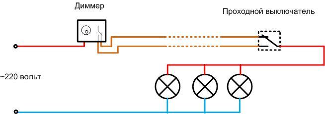
Walkthrough switches and dimmer
There is a lighting control scheme using walk-through switches. They form a system with which you can turn on and off the lighting independently from two points spaced apart in space. For example, it is convenient to turn on the light at the entrance when crossing a long corridor, and turn it off at the exit.
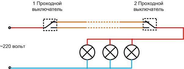
Such switches instead of one contact for closing-opening have a group of contacts for switching. With the advent of dimmers, the idea of \u200b\u200binstalling a dimmer in this circuit appeared. For example, to adjust the brightness level of the lamp depending on the environment.
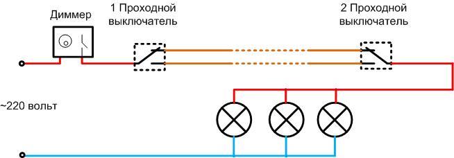
The dimmer can be installed on one side. At the same time, it can act as an additional light switch - if necessary, completely break the circuit.The best idea is to use a dimmer with a changeover group of contacts instead of one switch-switch - switching occurs when a key is pressed (turn-push type).
It is unlikely that it will be possible to install pass-through dimmers on both sides for two reasons:
- the design of the regulator does not provide access to the changeover contact;
- the first dimmer to the source will “cut” the sinusoid so that the effect of the second on the brightness will be unpredictable.
There is an unplowed field for lovers of experiments and alterations. The main thing is not to forget about safety.
Modular dimmer
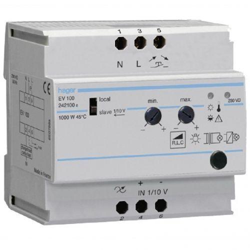
Such dimmers are used for lighting entrances and similar walkways. Their feature is that the regulator unit and the control button are separated in space. The main module is located, in most cases, in the switchboard. The control key is installed in any convenient place - at the entrance to the entrance, on the control panel, etc. The brightness control organ is located on the body of the main module, and the required level is set during adjustment.
With the exception of the most budget models, a modular dimmer may have additional service functions:
- memory (the next time you turn it on, the preset brightness level is saved);
- smooth rise and fall of light;
- the ability to set the rise and fall times for the highest level of illumination;
- other services.
The most advanced models can be assembled into master-slave (master-slave) systems.In this version, the illumination level is set on the main device, the rest follow it, controlled by the analog signal bus.
Desk lamp brightness control
Feature of use table lamp, floor lamp and other mobile lighting fixtures in that they can be plugged into any of the available sockets. Equipping each outlet with a separate dimmer is not the best way out. It is also not always possible to embed the regulator inside the device. It is much more convenient to use special-design dimmers designed for such purposes.
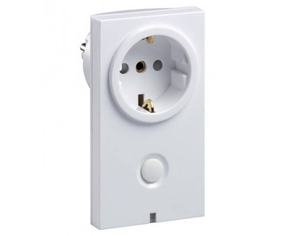
The dimmer adapter is inserted into a household outlet, forming the same connector with a glow level adjustment knob (touch-controlled devices are even more convenient). A floor lamp or table lamp is already included in it. If necessary, the dimmer can be moved to another location. Power strips with built-in brightness control are also available. The buyer himself can choose a convenient option.
Self-installation of the dimmer
Steps to replace the switch with a dimmer begin with the choice of a dimmer. Execution of the device - rotary, rotary-push, touch, etc. in this case is irrelevant. The first thing to start with the choice is the type of controlled lamps. It can be found in the instructions for the device or look for the lettering on the case.
| Letter marking | Symbol marking | Load type | controlled lamps |
| R | Ohmic | incandescent | |
| C | capacitive | With electronic control gear | |
| L | Inductive | Low voltage halogen lamps with winding transformer |
Many dimmers allow mixed loads (RL, RC, etc.).If you intend to dim fluorescent lamps, you need to make sure that their packaging is labeled "dimmable" (dimmed). Otherwise, the system will not work.
Important! Before attempting to connect an LED lamp, you must also make sure that it is marked "dimmable". If there is no such inscription, then a driver in the form of a current stabilizer is installed in the lamp, and an attempt to adjust the brightness by controlling the average current from the outside will be fruitless. This does not apply to LED strips - their current through the LED is limited by conventional resistors and the glow is well controlled by an external average voltage. That's why "non-dimmable" LED strips does not happen, despite the tricks of marketers.
The second important parameter is the maximum power. It should cover the total power of the switched luminaires with a margin. According to this characteristic, it is not necessary to choose a dimmer "on the verge". The rest is execution, design, etc. - to the taste and wallet of the buyer.

What needs to be prepared
Installation of a dimmer begins with the selection of a tool. At a minimum, you can get by with two screwdrivers:
- large for tightening (loosening) the petals of the dimmer (switch);
- smaller for clamping and loosening the wire clamps.
Will not be superfluous in this work:
- indicator screwdriver;
- multimeter.
You may need another small tool (fitter's knife, etc.).
Dismantling the standard switch
It is advisable to start installing any dimmer instead of a switch by checking the installation - you need to make sure that it is the phase wire that opens. In 99% of cases, it will turn out that the installation is done correctly. But it is necessary to exclude all surprises.If a negligent master put the switch in a gap of zero, then this will not affect the performance of the system without a regulator (unlike security). But the dimmer needs correct phasing. You can check this with a voltage gauge (indicator screwdriver). If everything is fine, then you can proceed to the next step. If not, then there is a lot of work to be done. And it’s better to think about whether dimming is worth it (safety is worth it, definitely).
The second, and very important step is to turn off the power to the lighting system. This is usually done at the switchboard.
Important! After disconnecting the switching element, it is imperative to check the absence of voltage directly at the workplace. Do not trust the diagrams in the shield and the inscriptions on the circuit breaker.
After making sure that the switch is not energized, it is necessary to remove the cover of the switch, loosen the terminals to which the wires fit, and the petals with which the switch bursts in the box. After that, the switching device must be carefully removed and the wires pulled out of the terminals. This must be done carefully so as not to break off the bare areas.
Short video instruction.
Dimmer installation
The regulator has the same dimensions and mounting dimensions. Therefore, the installation is carried out in the reverse order:
- the dimmer is installed in its seat;
- wires are connected to their terminals;
- by unclenching the petals, the regulator is fixed in the box;
- the screws of the terminals are tightened to fix the wires;
- the regulator cover is closed.
This completes the dimmer connection. You can apply voltage to the lighting system and try out the regulator in operation.