Scheme for manufacturing a simple LED stroboscope
Some car owners (tuning enthusiasts) retrofit their cars with a flashing light source - a strobe. This name is not very correct, in the technique of a stroboscope - a device for measuring rotational speed by visual comparison with the frequency of flashes. But the name stuck, the term stuck.
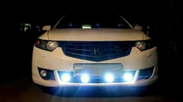
In a real environment, the stroboscope increases the visibility of the car even at night and in difficult weather conditions. This happens due to the peculiarities of human perception. Our senses, including the eyes, notice the change in the signal faster than its intensity. Therefore, flashes of light reliably attract the attention of other road users, even at relatively low brightness. You can make these lights yourself.
What you need to make a stroboscope
For the manufacture of a stroboscope, the following components will be required:
- Actually lanterns. You can use ready-made lights (for example, it is easy to purchase a set of daytime running lights).You can assemble something homemade (based on foglights, etc.). Of course, strobe lights are built on LEDs. It makes no sense to use incandescent lamps, and it's not just about current consumption. The life of a traditional light source filament depends on the number of times it is turned on and off. Therefore, in flashing mode, such a lamp will not last long.
- Control board. Can be built on a different element base.
- Additional elements - fuse and switch (latching button or toggle switch). The fusible element can be used as a backup, if there is one in the car, or an additional one can be supplied. A switch is not required, but highly recommended. It should be possible to turn off the strobe (for example, so as not to annoy the traffic police). The button or toggle switch can be mounted on the car panel in any convenient place.
For installation, a metalwork tool is required - it is selected locally, depending on the method and place of installation.
Scheme of a stroboscope on a car
The block diagram of the stroboscope is shown in the figure.
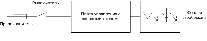
It may differ slightly if the control board supports separate control of the lights on the right or left side of the machine.
You can buy the board (for example, in online stores), or you can make it yourself. Its manufacture is available even to a novice radio amateur.
On tl494
The control board can be built on the common TL494 chip. It is a PWM controller, but it can be used as a pulse generator with different duty cycles and frequencies. Parameters are controlled using external elements.
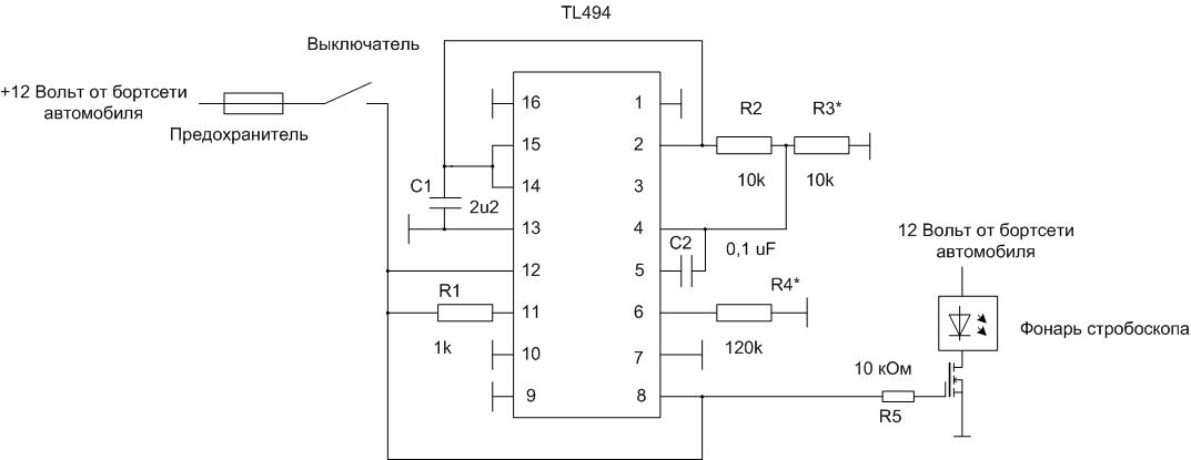
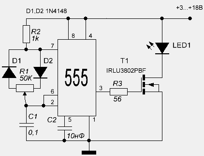
By selecting the value of R4, the flashing frequency is set, by selecting R3, you can adjust the duration of the flashes. Instead, you can mount multi-turn trimmers and adjust the blinking parameters with them. As a key, you can use both field-effect and bipolar transistors for the corresponding drain (collector) current.
Important! In this and subsequent circuits, attention should be paid to the presence of current limitation through the LED strobe light - drivers or ballast resistor. If there is no current-limiting device or circuit, a resistor of the appropriate resistance and power must be connected in series with the lamp.
Other options
A very simple control board can be made on the K561LA7 chip (foreign analogue of CD4011A). This chip is very common and costs a penny. Making armor is available even to an amateur with primary radio design skills. The flashing frequency is set by a resistor and a capacitor. The greater the capacitance and resistance, the less often the lights flash. You can roughly calculate the frequency using the formula F=0.52/(R*C). You can finally set the blinking period by selecting the parameters of the elements of the timing chain. Another option is to install a tuning resistor instead of a constant one and select the desired mode by rotating it. Instead of K561LA7, you can use the K176LA7 chip, but it is more sensitive to the supply voltage. You can also use any K176 and K561 series microcircuits containing NOT, AND-NOT, OR-NOT elements.
For any scheme, it is necessary to provide for the installation of an output transistor on a heat sink.
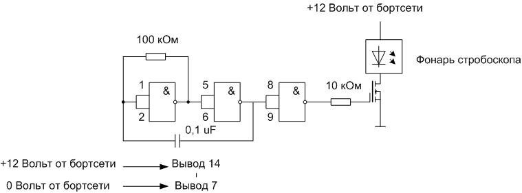
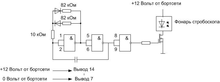
The circuit can be slightly complicated by adding a few details and separating the charge and discharge circuits of the capacitor. Flash and pause times can now be adjusted separately.
You can also use the widely used NE555 chip (KR1006VI1). It is designed to build such circuits and has a simple inclusion with a minimum of additional elements.
But the best lighting effects can be achieved with a microcontroller. You can use the "baby" Attiny13 or the Arduino Nano board, adding to them only a key on a powerful transistor (field or bipolar). You can choose the type of transistor from the table or choose your own.
| Transistor name | Type of | Maximum drain/collector current, A |
|---|---|---|
| BUZ11A | Field (N) | 25 |
| IRF540NPBF | Field (N) | 33 |
| BUZ90AF | Field (N) | 4 |
| 2SA1837 | Bipolar (n-p-n) | 1 |
| 2SB856 | Bipolar (n-p-n) | 3 |
| 2SC4242 | Bipolar (n-p-n) | 7 |
Code in Arduino or C++ can be written even by a novice programmer. Control flashing LED as an exercise is offered at the very first lessons on programming microcontrollers. Having mastered the skills a little, you can proceed to the further development of the program. It is possible, for example, to build a cyclic switching of the blinking frequency with a tact button or a change of lighting effects. Everything is limited by the imagination of the program developer.
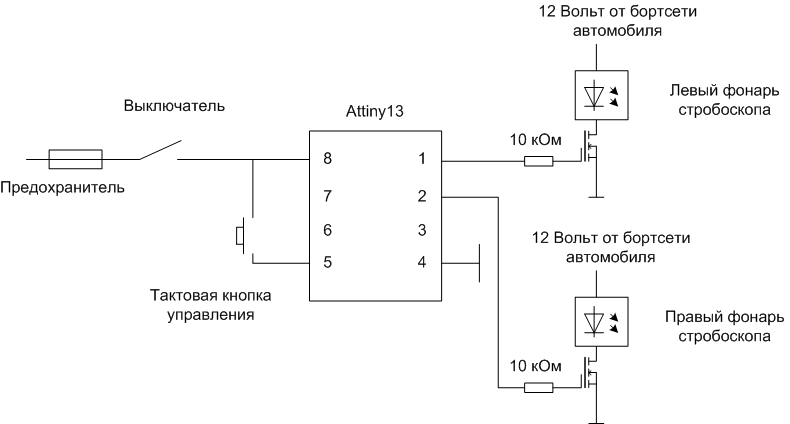
The figure shows an example of a circuit on Attiny13, but you need to understand that connecting external elements to the legs of the microcircuit may be different - the pin assignment is selected programmatically.
How to assemble a stroboscope
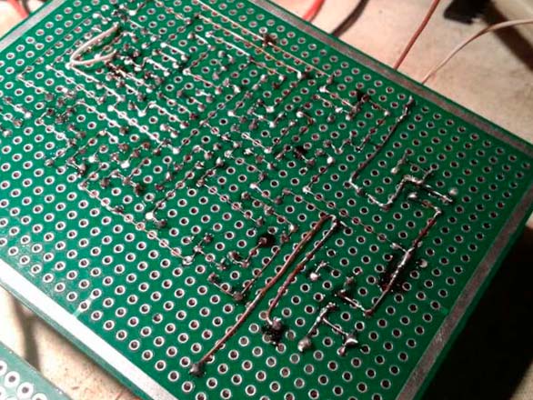
Assembly begins with the manufacture of the control board. Those who are familiar with home technology can design and etch the board themselves. The rest is easier to assemble the circuit on a piece of breadboard. Solderless payment cannot be applied - shaking and shocks, which inevitably accompany driving a car, will lead to a breakdown in contacts and failure of the circuit.
For key transistors, it is necessary to install small radiators or provide the possibility of attaching an external heat sink. To do this, the key elements must be placed on the edge of the board with heat-removing surfaces facing outward. After assembly, you need to determine the location of the board. Most likely, it will be mounted in the engine compartment. Then you need to pick up or make a casing that protects against dust, dirt and moisture. In this case, it is necessary to ensure efficient heat removal from transistors, therefore wrapping the board in heat shrink is not a good idea. Then you need to choose a place to install a control toggle switch or button, find a backup fuse or mount an additional one (it is convenient to use fusible elements that can be installed in a wire break). After that, it is necessary to lay the conductors and make the connection according to the electrical diagram.
Health check
You can pre-check the assembled strobe board for operability without installing it on a car. To do this, instead of a flashlight, you need to connect to it a single LED with a resistor connected in series and supply 12 volts (you can use it from a power supply or from a car battery). The LED should flash. Here you can also configure the board by selecting the values of the frequency-setting elements.
A final check is made after installation is complete.To do this, use a toggle switch or button to turn on the power of the stroboscope, visually check for flashes.
What are the manufacturing errors?
Most errors come down to incorrect installation. To avoid them, during assembly, you must carefully monitor the correct connection of wires and soldering of electronic components. With error-free installation and preliminary check of the board, everything will start working immediately after power is applied.
After installing the strobe, the first thing to do is to visit the traffic police department to register the changes - the installation of any lighting devices that are not provided for by the design requires such a procedure. Otherwise, you will have to travel from one traffic police post to another, collecting fines. It must be remembered that the installation of flashing lights of red and blue is prohibited. They can only be mounted on vehicles of special services. It will not be possible to legalize their installation.