How to connect a chandelier to a two-gang switch
The switch with two keys has been popular since ancient times. With it, you can control two lighting fixtures from one point (for example, turn on different lighting zones) or control the brightness of one chandelier by switching more or fewer lamps. Connecting a chandelier to a double switch is easy to do on your own, for this you need to understand a few points.
Switch device with two keys
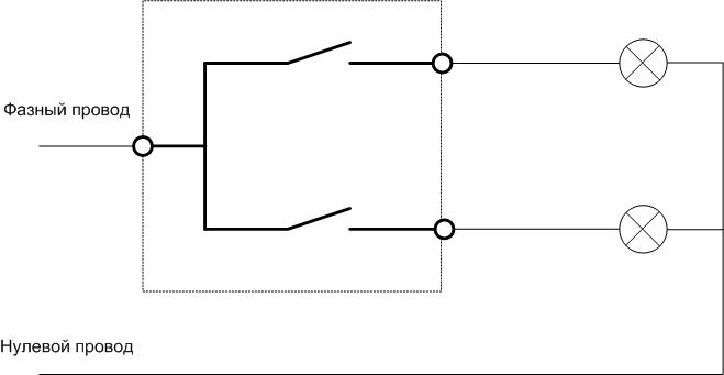
The two-gang switching element consists of two circuit breaks controlled separately. Each switch is covered with a decorative key made of insulating material (plastic). There are three terminals for connecting loads - one common and two separate. A phase wire is supplied to the common terminal, from separate - two conductors to the loads. They can connect in parallel - you get another application of such a device, non-standard. In this case, the switched current will double relative to the passport one. And the keys must be connected mechanically in an inconspicuous place so that both channels are switched simultaneously. If not connected, then you can turn on the load with any key, but there will be no increase in load capacity.
Important! When connecting switches in parallel to increase the load capacity, it is necessary to check whether the cross section of the outgoing wire (or wires) is designed for an increased load.
There are two main types of connecting contacts for household switches - screw and plug. If a stranded wire is used for screw connection, its part, freed from insulation, must be irradiated or terminated with crimp lugs.
Just like in a single-key device, a two-channel switch can have a backlight based on LEDs or halogen lamps.
Connection steps
Work on connecting the lamp to such a switching device consists of several stages. Each stage matters, creates its own contribution to the overall success. Therefore, the work must be carried out sequentially, without missing a single stage.
Ringing and marking
When an electrician gets to work, he has hidden wiring as his starting point - a few wires going into the wall and a few coming out of the ceiling. It is very important to know exactly which beginning of the wire corresponds to which end. This is necessary both in terms of the correct connection of the lamp, and in terms of safety.
The wires must be called out, and if there is no color coating of the conductor insulation, mark.Dialing must be done even when the installation is done with colored wires - it is not a fact that the ideas about the correctness of the laying are the same for those who laid the wiring and those who connect the chandelier. For dialing need multimeter and auxiliary wire. It is forwarded for the duration of this work between the beginning and end of the tested conductors.
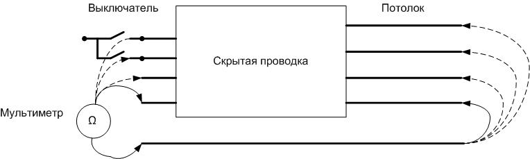
For one electrician, it is better to search for wires in sound continuity mode. By connecting the multimeter on one side, on the other hand, the auxiliary wire is looking for the same conductor, waiting for a sound signal. Having found the matching sides, the wire is marked and moved on to the next one.
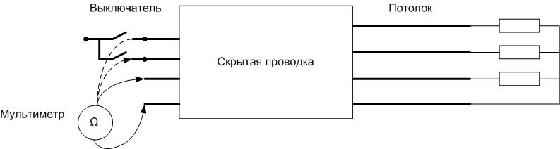
If the auxiliary wire cannot be laid, there is another way. You will need several resistors with very different values. For example, 510 Ohm, 1 kOhm, 10 kOhm. They must be connected from the far side and measured with a multimeter resistance from the opposite edge. According to the measured values, they make up a picture of the location and produce marking.
Dangerous! The dialing procedure must be performed only when the voltage is off! Turning off the light switch is not enough, you have to open the circuit earlier - at the switchboard.
Grouping wires
Depending on the number of lamps in the chandelier, they are grouped differently. The two-lamp luminaire has separate inputs for each lamp. This allows you to get combinations using a switch with two keys:
- the chandelier is off;
- the first lamp is on;
- the second lamp is on (they can be of different power or different colors);
- two lamps are on.
For a different number of lamps, the combinations may be different. And the grouping of wires must be clearly understood before installation.
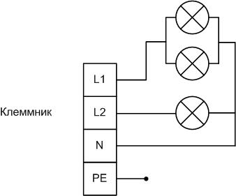
In a three-arm chandelier
A three-arm chandelier has one group of two lamps connected in parallel and a separate single element. They are connected according to the scheme with a common wire, to which the neutral conductor is connected. Each group of lamps has its own phase output, through which it can be powered independently of the others.
By combining the switching of the circuit breaker, you can get options:
- the lamp is off;
- one lamp is lit;
- two lamps are lit;
- all three lights are on.
So you can control the illumination of the room or create decorative lighting by combining multi-colored radiating elements.
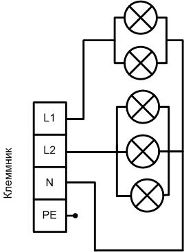
In a five-horned chandelier
The five-arm chandelier does not differ in particular variability from the previous version. The possibilities of a two-channel switch give combinations similar to the previous option:
- completely off chandelier;
- two lamps are lit;
- three elements are included;
- the chandelier is fully turned on.
The difference from the previous version is only in the number of lamps, which allows you to have brighter lighting. But we must remember that there is a rule that says that one lamp with a power of 100 W gives more light flowthan two 50 watts. It applies not only to incandescent lamps, but also to LED elements.
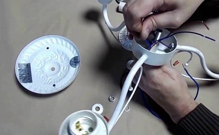
The video clearly shows the connection of wires in the chandelier
Choosing connection options
If the connection of the chandelier was planned at the stage of the overhaul of the premises, then the connection options, most likely, were thought out in advance.But in many cases, you have to install a chandelier in a room with finished wiring. And here there may be various options - a different number of wires can come out of the ceiling.
From the ceiling 2 wires
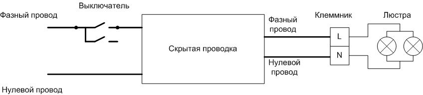
This situation is possible in old apartments. Of the two wires, one will be phase, the other zero. There is no difficulty here. Just connect two wires to the lamp. But if the chandelier is with separate groups of lamps, they will have to be connected in parallel. If the chandelier has a marking of the phase terminal and zero, then you must follow the connection diagram. For incandescent lamps, this does not matter, but if the burnt out "Ilyich's light bulb" has to be replaced with an LED device, then phasing is critical here. The LED light may flash or glow dimly with the switch in the off position.
On the switch side, you can connect a phase wire to one switching channel, or you can connect both breaks in parallel. In the first case, you will have to manipulate with one key. If the working channel fails during operation, the outgoing wire can be transferred to another terminal and the switch can be operated further.
Important! In this option, it is especially necessary to make sure that it is the phase wire that is being switched, since in the old rooms the color marking of the wiring was not provided. You can do this with indicator screwdriver.
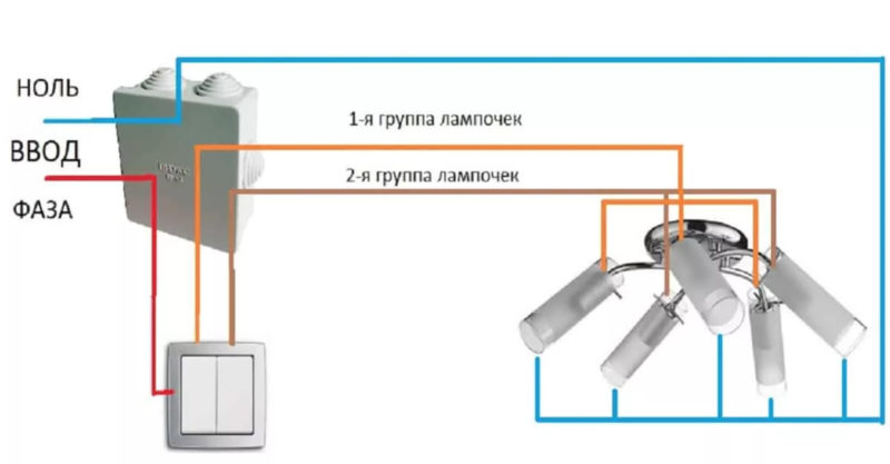
From the ceiling 3 wires
The case with three wires provides two options.
In the first variant in new houses, most likely, these are phase, common and ground wires, indicated, respectively, by colors:
- red (brown) (on the terminal block - L);
- blue (on terminal block N);
- yellow-green (PE).
In this case, it is necessary to connect the wires according to the marking. If there is no terminal for the ground wire, then this is a product of safety class 0 (zero), and the yellow-green conductor does not need to be connected anywhere.
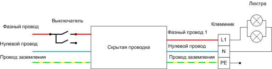
Important! If the lamp has I protection class and a terminal for connecting the ground conductor, it is strictly forbidden to leave the ground wire unconnected! Such a chandelier will work, but in terms of protection against electric shock, it will have a serious flaw. The safe operation of such a device is ensured precisely by the presence of a connection to the ground. Therefore, it is impossible to operate such a lamp in systems where there is no grounding!
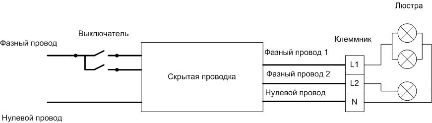
The second option occurs in old houses. A neutral wire and two phase wires go to the lamp from the switch. Here you can connect a chandelier of protection class 0. Zero wire to the zero terminal, two phase wires to different groups of lamps.
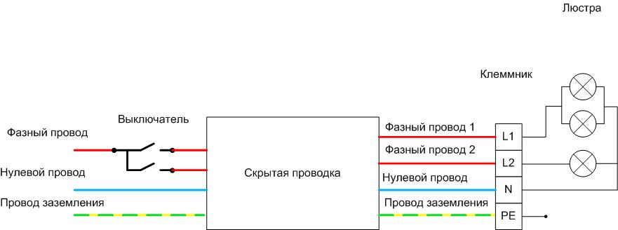
From the ceiling 4 wires
This option is the best in terms of functionality and connection security. Here are:
- zero conductor;
- two phase for connecting two groups of lamps;
- protective earth wire.
The chandelier is connected according to the marking of the terminal block.
How to convert a chandelier designed for a single switch
If the luminaire contains two or more lamps, but is designed to work with a single switching element, you can try to convert the chandelier connection to two separate switches. The process is easier to consider using the example of a chandelier with three elements.
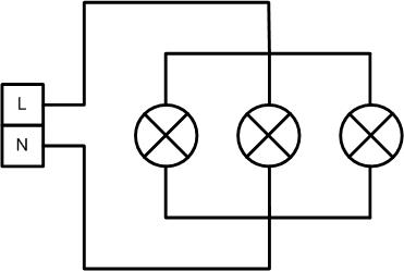
Initially, the schema looks like this:
- three lamps connected in parallel;
- two-terminal terminal.
The PE conductor and its terminal are not shown for simplicity, but they must be kept in mind. Alteration to produce in the following sequence:
- Find the connection point of the phase conductors.
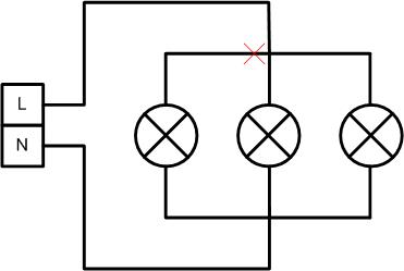
- Disconnect one lamp from the node.
![One lamp off]() Turn off one lamp.
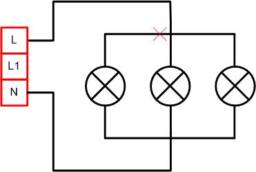
Turn off one lamp. - Replace the terminal with a four-terminal one (one terminal for the ground wire).
![Replacing the terminal block]() Terminal terminal replacement.
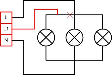
Terminal terminal replacement. - Lay an additional conductor and connect it to the additional terminal.
![The final scheme of the chandelier.]() The final scheme of the chandelier.
The final scheme of the chandelier.
The maximum permissible load for a wire with a copper core at a supply voltage of 220 V is indicated in the table.
| Wire section, sq. mm | 0,5 | 0,75 | 1 | 1,5 |
| Permissible load, W | 2400 | 3300 | 3700 | 5000 |
Obviously, 0.5mm2 wire is sufficient for most loads that can be encountered in an incandescent chandelier and for any reasonable number of LED elements. That's why there is no reason to choose a conductor with a large cross section.
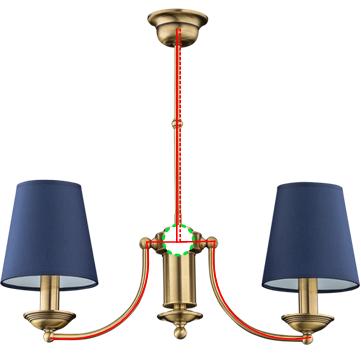
For example, a three-arm chandelier is shown, in which the connection node is located in the place indicated by the green dotted circle. The laying of the additional wire is indicated by the red dotted line. It is placed in the same tube as the main conductor.
The success of an event depends on two factors:
- accessibility of the junction of phase wires;
- availability of space for laying an additional conductor of the required section.
In conclusion, the video: a master class on connecting the lamp to a double switch.
If everything went well, then connecting a two-gang switch to a converted chandelier using the methods described above will not cause difficulties.