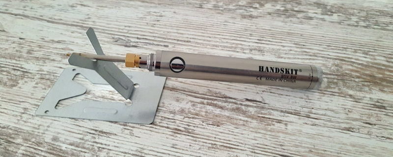
Description and manufacture of voltage indicator
In case of electrical malfunctions, short circuits, sparks or broken wiring, it is not necessary to call an electrician. In most cases, you can manage on your own. To quickly identify and correct breakdowns, a small-sized device is needed - a voltage indicator. You can buy it at the store or make your own.
The principle of operation of the voltage indicator
People often don't understand how the device works. An electrician or user sticks the tip of the device into one hole of the socket, then touches a metal plate on its body with a finger, and the LED (or neon light) lights up.
Thematic video: Hidden features of the indicator screwdriver
But to turn on the lamp, you need two conductors through which current flows, and the indicator works when you touch one end of the power cord or socket contact with a sting. The secret is that the other wire in this case is the human body. It is one of the plates of a huge capacitor - the earth.
The phase current goes through the sting of the indicator to the resistance and then to the LED. When a finger touches the sensor plate connected to the second terminal of the semiconductor, zero potential is applied to it and the light source lights up.
Required materials for the manufacture of the indicator
To make a simple LED device that indicates phase or voltage (approximately), you need to find a working circuit. Then buy or get the following parts and tools:
- LED of any type;
- a diode that opens with a current of 10-100 mA at a forward potential of 1 V, with a breakdown voltage (reverse) of at least 30-75 V;
- resistor 100-200 kOhm;
- bipolar transistors;
- soldering iron;
- wires;
- metal plate (can be cut from a beer can);
- plastic case, preferably transparent;
- sting, you can take an ordinary nail.
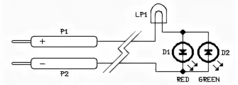
LED phase indicator circuit
According to the drawing, the device is assembled. A simple indicator for checking the phase consists of 3 parts. It can be assembled in 5-10 minutes. Devices that can roughly indicate voltage include transistors and special LEDs.
At 12 volts
The LED indicator circuit for determining the car charge voltage contains 16 parts.
Three voltage dividers are installed in the device: on resistors, zener diodes and transistors. Their outputs are connected to a three-color LED.
Voltage (in volts) is determined by the color of its glow:
- red - more than 14.4;
- green - 12-14;
- blue - less than 11.5.
The indicator consists of the following parts:
- fixed resistors R1, R3, R5 and R6 - 1, 10, 10 and 47 kOhm, respectively;
- potentiometers R2, R4 - 10 and 2.2 kOhm;
- zener diodes VD1, VD2 and VD3 for 10, 8.2 and 5.6 V;
- bipolar transistors VT-VT3 type BC847C;
- LED - LED RGB.
Potentiometers R2, R4 set the lower and higher voltage limits.
Thematic video: How to make a do-it-yourself hidden wiring detector from improvised materials
The circuit works like this:
- at a low input potential, the transistor VT3 opens, and VT2 closes (blue color is on);
- at rated voltage, current flows through parts R5, VD3, R5 to a green crystal (VT2 is open, and VT3 is closed);
- when the potential is high, the divider R1, VD1, R2, VT1 turns on and lights up red.
At 220 volts
To protect yourself from electric shock, you need to put a resistance with a large value at the input of the indicator. The general scheme of the indicator is as follows:
- one terminal of a 100-200 kΩ resistor is connected to the sting;
- the anode of the diode and the cathode of the LED are soldered to the other end;
- their remaining legs are connected to a metal plate.
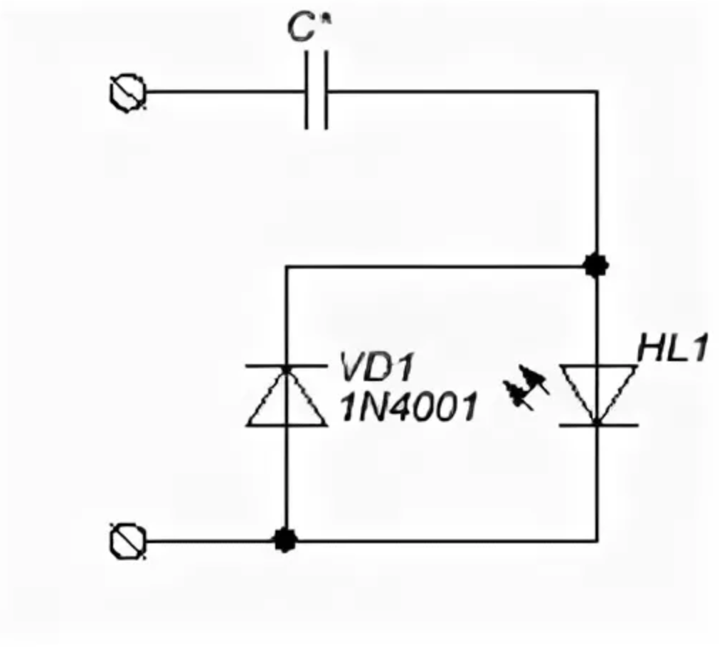
The diode in the circuit can be of the type KD521, KD503, KD522 (analogues 1N914, 1N4148). To make a voltage indicator on LEDs with your own hands at 220 V is within the power of any master.
How to make an LED voltage indicator
Most users assemble a phase indicator device inside a medical syringe. Its body is transparent, and it is not necessary to drill a hole in order for the light of the semiconductor to be visible.
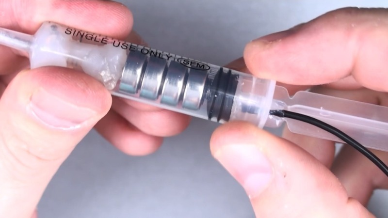
Make an indicator like this:
- Disassemble the syringe.
- The sting is his needle. One end of the resistor and other parts are soldered to it (according to the diagram).
- A thin wire is attached to the legs of the diode and LED going to the plate and brought out.
- Cut off the inside of the plunger and insert it into the syringe.
- The wire is soldered to the plate.
- The plate is glued to the body on the side or on the top of the piston.
Recommended for viewing: Options for making homemade probes
The battery voltage indicator is assembled by surface mounting or on the board. It is inserted into a larger syringe or a suitable box in which a hole is made for the LED. Solder two wires with clips to connect to the battery.
At the end, using a voltage regulator and a multimeter, set the minimum and maximum voltage limits. This is how the indication is obtained.