Light sensor connection diagram
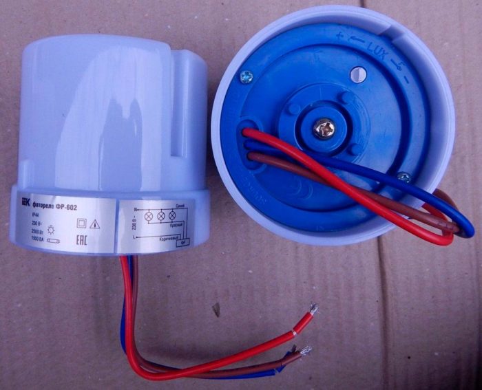
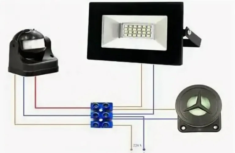
For automatic control of external (and sometimes internal) lighting, it is convenient to use a photorelay. When the level of natural light decreases in the evening, it will turn on the artificial lighting system and turn it off in the morning when the sun rises. If you combine a photo relay with a motion sensor, you can get even greater savings - the light will turn on only at night and only if a person is present. There are many similar combined models on sale. You can select and connect a day-night sensor yourself.
What is a photorelay, device and principle of operation
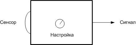
If we consider the photorelay as a "black box", then its device and principle of operation are simple:
- on the input side, a sensitive element where the light enters;
- at the output - a signaling device;
- on the body - a tuning organ.
When light hits (or stops hitting) the sensitive sensor, the device generates a signal that can be used to control actuators, lights (directly or through a repeater relay).
You can send a signal to the control panel or trigger an alarm. The signal can be in the form:
- voltage level changes (logic level);
- "dry contact" relay;
- changes in the state of the electronic key (open collector transistor), etc.
The light detector can be built into the body of the device, or it can be remote. Then it can be installed in any convenient place. The setting organ allows you to adjust the level of operation - you can make the relay turn on the light earlier or later.
In fact, the photorelay device is more complicated.
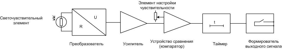
In general, the device contains:
- light-sensitive element (photoresistor, photodiode, etc.);
- conversion device (converts a change in the state of the sensor into a change in electrical voltage);
- buffer amplifier;
- threshold device - compares the voltage from the sensor with a given level;
- timer - limits the time of lighting operation;
- output signal conditioner.
Devices from different manufacturers have different circuitry. Some elements may be combined, some may be missing. Some devices have a fixed response level, they do not have an adjustment body.
Important! The photorelay is often referred to as a light sensor, light sensor, day-night sensor, etc. These names are not entirely correct.A light sensor, strictly speaking, is a part of a photo relay that converts the level of illumination into an electrical signal or into a value that can be converted into an electrical signal.
Important technical parameters and varieties
Before choosing a photorelay, it must be completely clear where it will be installed and what load to control. Based on this, when buying, you need to pay attention to the following technical characteristics.
- Supply voltage. Can be AC 220 volts or low DC (12, 24 volts, etc.). Selected from the convenience of connection at the installation site.
- Sensor design. The light detector can be remote or built-in. Remote can be mounted a few tens of meters from the main unit.
- Degree of protection. Specifies the mounting location. If, for example, the device has a degree of protection IP20, then this implies installation only in a room (in a switchboard) and a remote sensor.
- load capacity. Determines the electrical power that can be directly switched by the photorelay.
- Turn-on threshold change range. Specified in lux. It does not carry particularly useful information, because it is difficult to determine by eye what level of inclusion is needed on the spot. The wider the range, the better.
- Delay on or off. From zero to several tens of seconds is enough for all occasions.
- Also, among the parameters, the own consumption of the device is indicated.. It is small, in most cases does not exceed 5-6 watts. Therefore, there is no point in chasing this parameter.
| photorelay | Load capacity of the contact group |
| FR-2M | 16 A (220 VAC, 30 VDC) |
| FR-1 | 6 A (380 VAC) |
| FR-601 | 10 A (220 VAC) |
| FR-602 | 20 A (220 VAC) |
| FR-M02 | 16 A (220 VAC) |
Based on these characteristics, you can choose a relay that is optimal in terms of a combination of technical and price parameters.
Photorelay connection diagram
The wiring diagram for the light sensor is simple. In fact, this is a light switch, and it must be connected according to the same principle. But the photorelay has features that, during installation, can pose certain tasks.
Connection in TN-C and TN-S networks
Currently, 220 volt networks are operated in Russia, in which the protective (PE) and neutral (N) conductors can be combined (TN-C) or separated (TN-S). The TN-S system is considered more progressive and correct, but a full transition to it will not happen soon.
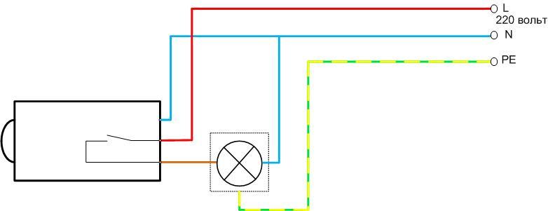
Photorelay in a two-wire TN-C network
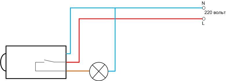
The difference from a conventional light switch is that a neutral wire must be connected to the photo relay. This is necessary to supply power to the internal control circuit of the twilight sensor. If the sensor supply voltage differs from 220 volts, then it is not necessary to connect it to the neutral wire, but an external source of the required voltage will be required.
Photorelay in a three-wire network TN-S
There is an additional PE wire in the TN-S network. The design of almost all photorelays does not provide for the connection of this conductor, so the circuit will not change.
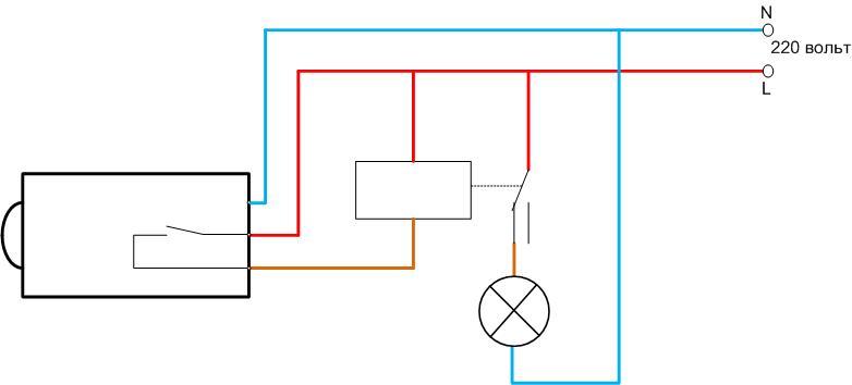
Connecting a light sensor through a repeater relay
In some cases, the load capacity of the own contact group of the light sensor may not be enough to switch the existing load. In such a situation, the output of the device must be boosted with the help of an intermediate relay, the functions of which can be performed by a magnetic starter.Its contacts must be designed for the full current of the lighting device. The photorelay output must be connected to the starter winding. And the switching of the power supply of the light bulb will be performed by the contacts of the repeater relay.
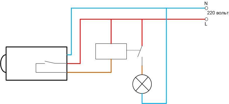
Output Inverting Circuit
There are situations when the control of the lighting device must be carried out according to the inverse principle - turn on when natural light appears and turn off when the sun sets. Such a photorelay-repeater may be needed, for example, when working in a lighting system for rooms that do not have windows (for keeping livestock, etc.). It is not difficult to implement it, the light sensor connection scheme is almost the same as the previous one. You only need a starter with a changeover contact group.
In the absence of a signal from the light sensor, the lamp is powered through the normally closed (normally closed, NC) contacts of the repeater. If the relay is triggered by the light flux, the starter will supply power to the light bulb. When darkness falls, the lights will turn off.
Scheme with an additional switch
The standard circuit can be equipped with an additional switch. Then the lighting can be turned on or off regardless of the state of the photo relay - depending on the selected option. This may be necessary in the event of a photocell failure.
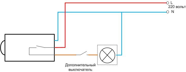
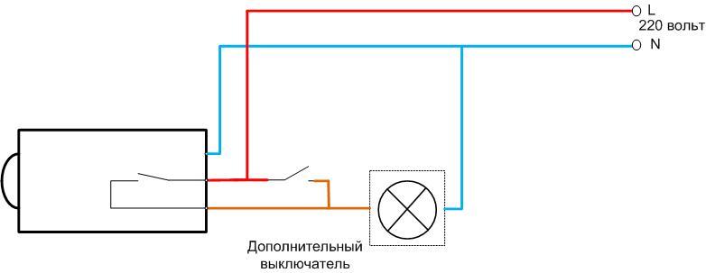
If a repeater relay is used in this option, then an additional switch must be installed parallel his contacts. It is even better to supplement the circuit with a three-position switch. It will help you choose the lighting mode - manual or automatic. The complete wiring diagram will look like this.
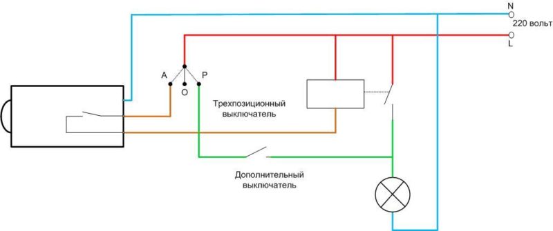
Mode O allows you to completely disable lighting.
Installation and installation of a photorelay
First of all, it is necessary to determine the installation location of the photosensitive sensor. To do this, you must follow a few simple rules.
- Do not install the photo sensor where it can be exposed to light from artificial sources (street lighting, headlights of passing cars, etc.). This will turn off the lights. The worst option is when the photosensor is illuminated by a controlled lamp. You will get a feedback circuit: darkness has come - the lighting has turned on - the light has hit the photorelay - the lighting has turned off, darkness has come - .. and further in a circle. In this case, one cannot speak of any comfort.
- Do not install sensors in the shade. In this case, there will be an early switch-off and a late switch-on.
- It is necessary to protect the sensor lens from dust and dirt and install the device in such a way that contamination of the sensor is excluded. If this is not possible, at least the inlet of the detector should be cleaned regularly. Otherwise, the sensitivity of the device will decrease.
- If a relay with a remote sensor is used, the maximum installation distance should not be exceeded.
At the end of the video: Install the photorelay for night lighting.
Installation of electrical circuits must be carried out with a cable with copper conductors. For reasons of mechanical strength for external wiring, its cross section must be selected at least 2.5 sq. mm. In 99+ percent of cases, such a cable or wire will pass under maximum load conditions. Before switching on for the first time, carefully check the correct installation. After that, you can turn on the lighting system and start setting up.