Scheme of connecting the motion sensor to the LED spotlight
The use of a motion sensor in conjunction with a street lighting spotlight in many cases allows you to get significant energy savings. The sensor detects the presence of people or cars in places where their stay is not permanent - in the entrance of a residential building, in the passage between garages, in warehouses. The command to turn on the lighting is given only when it is necessary. If the project does not provide for such a detector, you can connect the motion sensor to an outdoor or indoor LED spotlight yourself.
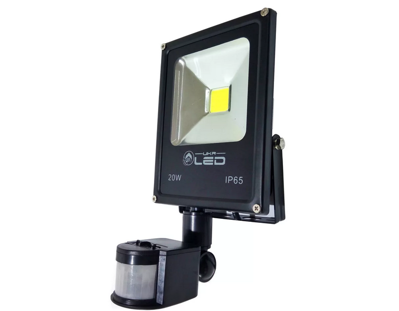
Spotlight options with motion sensor
At the moment, there is an active displacement by LED spotlights of lighting devices built on a different element base - incandescent lamps, halogens, etc. Within the framework of the topic under consideration, there is no fundamental difference between them - connecting a motion sensor to any spotlight is the same. But the low power consumption of LED devices in many cases allows, when connecting sensors, to get by with their own contact group and not to increase the load capacity with intermediate relays.
It is advisable to choose motion sensors combined with photorelay. It will turn off the spotlight during daylight hours and additionally save electricity without manual control. This will not affect the wiring diagram. It is also convenient to use detectors with an adjustable turn-off delay in order to leave the monitored area with the lights on.
How to connect a sensor to a spotlight
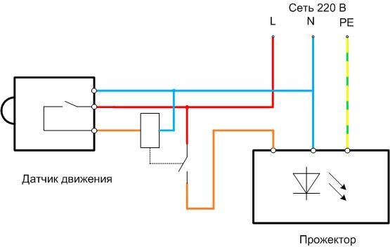
The output contact group of the detector serves as a searchlight power switch. But connecting the sensor with two wires will not work - most sensors need 220 volts (with the exception of battery-powered devices). Therefore, you will have to pull three conductive wires to the motion detector:
- phase;
- zero;
- power line from the sensor to the spotlight.
Ground is not needed for most sensors. Therefore, you can use a three-core cable. It is better to find a cable with different colors of core insulation, but not containing a conductor with a yellow-green marking used for PE lines. This will not affect the performance of the system, but in the future it may mislead specialists during repair work.
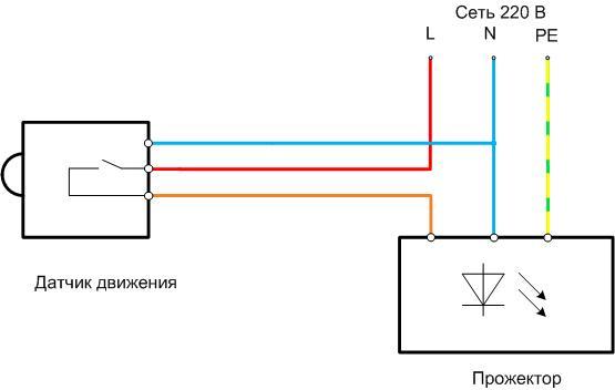
The final diagram looks like this. The cable cross section is selected from the conditions:
- the cable must be designed for the full power consumption of the spotlight;
- the voltage drop across the double length of the line must not exceed 5% (or better - even less), otherwise light flow searchlights will noticeably decrease;
- for reasons of mechanical strength, the cross section of the conductors should not be less than 2.5 sq. mm.
The bandwidth of copper wires with different cross-sections is indicated in the table. Aluminum for the arrangement of lighting systems should not be used.
| Conductor cross section, sq. mm | Maximum power at a voltage of 220 V, W | |
| With open laying | When laying in pipes | |
| 0,5 | 2400 | - |
| 0,75 | 3300 | - |
| 1,0 | 3700 | 3000 |
| 1,5 | 5000 | 3300 |
| 2,0 | 5700 | 4100 |
| 2,5 | 6600 | 4600 |
| 4,0 | 9000 | 5900 |
The table shows that a conductor with a cross section of 2.5 sq. Mm. in the worst case, it is enough to provide energy for a 4600 W luminaire. When using LED floodlights, this is enough to create a luminous flux equivalent to that created by an incandescent lamp of about 36,000 watts. That's why 2.5 square cable (minimum mechanical strength) covers 99+ percent of reasonable needs in the power supply of lamps. And only in the case of very long lines and very powerful consumers, it may be necessary to increase the cross section to 4 sq. mm. It is most convenient to check the line for voltage losses using online calculators. Initial data required:
- full length of the line (from the power point to the sensor and from the sensor to the spotlight);
- section and material of conductors;
- load current (spotlight power).
It is even better to assemble a circuit with the ability to output to manual control mode and an additional switch. To do this, you need a three-position switch.
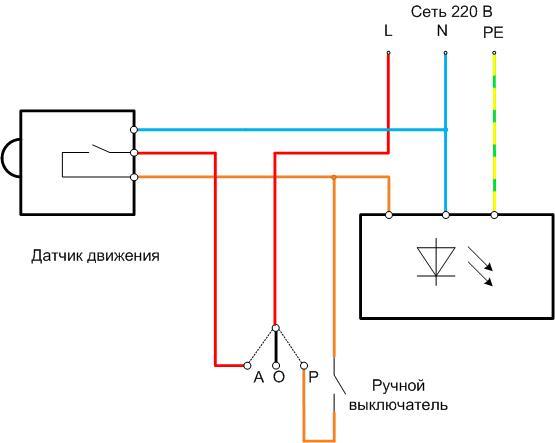
When the switch is set to manual mode (P), the lighting can be controlled using an additional switch. This fashion will not be superfluous in the event of a photo relay failure - for the duration of the repair.Position O is used to deactivate the system. If this mode is not needed, a switch with two positions (P-A) can be dispensed with. The mode select switch and manual switch can be located in a separate lighting control panel.
If the contact system of the motion sensor does not allow switching the full load of the floodlight, you will need to turn it on through a repeater relay, which can be used as a starter.
The starter can also be located in the shield. A circuit with an intermediate relay and a three-position switch can be combined.
Connecting multiple sensors to one spotlight
There are situations when it is required to control several zones to control one spotlight. For example, two entrances to a garage complex, or a car entrance and a pedestrian entrance. It may happen that one sensor cannot cover all zones. In this case, it is necessary to install several sensors so that each monitors its territory. When connecting such sensors, two options are possible:
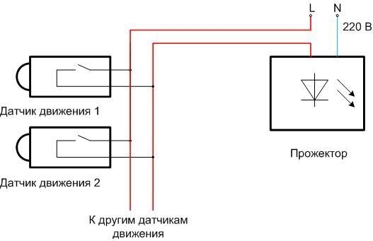
- When the output contact group of each sensor is designed to switch the full power of the spotlight, the contacts can be connected parallel (scheme "mounting OR").
![Scheme of connecting the motion sensor to the LED spotlight]() Connecting two or more sensors directly to the floodlight (N conductor to the sensors is not shown for simplicity).
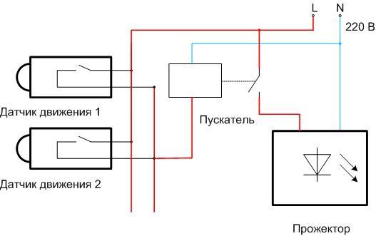
Connecting two or more sensors directly to the floodlight (N conductor to the sensors is not shown for simplicity). - If the load capacity of the contact group of at least one or more detectors does not allow working with the selected projector directly, the sensors are also connected according to the "mounting OR" scheme. But they control the illuminator through an intermediate relay or starter.
![Scheme of connecting the motion sensor to the LED spotlight]() Connecting two or more sensors to the searchlight through a repeater relay (N conductor to the sensors is not shown for simplicity).
Connecting two or more sensors to the searchlight through a repeater relay (N conductor to the sensors is not shown for simplicity).
Important! It is a bad idea to connect in parallel, without an intermediate starter, two motion sensors that control the same zone in order to "increase the load capacity" of the contact groups. No amount of adjustment will be able to achieve perfect simultaneity of the sensors. This will cause one of the detectors to turn on earlier. As a result, both contact groups will fail.
Setting up the detector and eliminating false positives
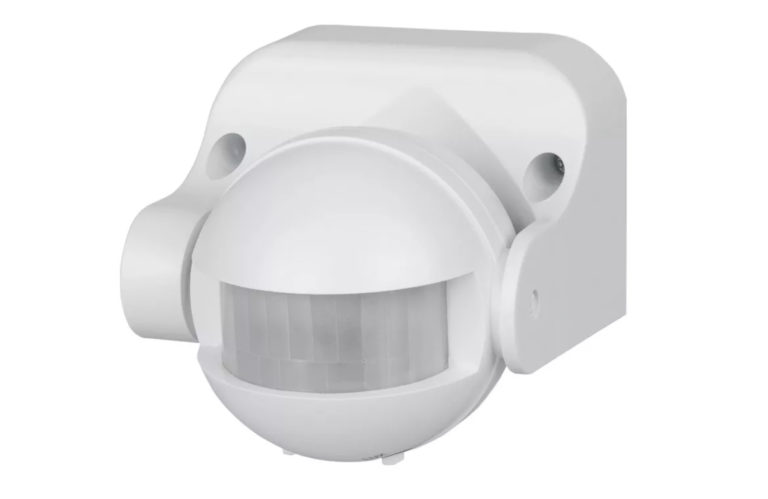
The motion sensor is configured according to the manufacturer's instructions. It must be read before the system is put into operation.
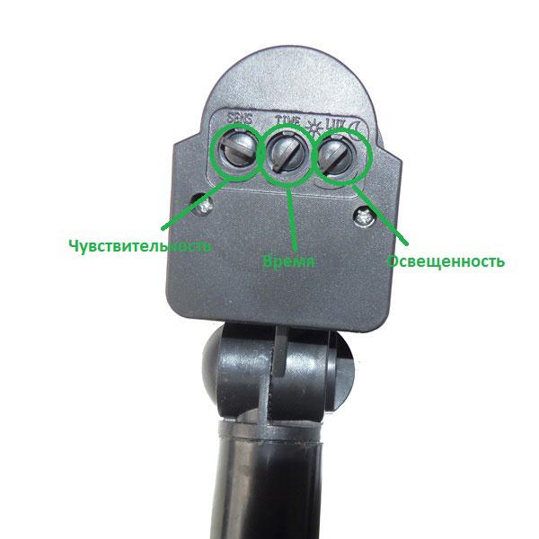
- In most cases, you will have to adjust the sensitivity of the device - so that it does not react to small animals, flying birds, small objects carried by the wind, etc. Sensitivity adjustment is made for the sensor of any type.
- Some sensors have a turn off delay setting. This function is convenient to ensure that a person or a car can leave the sensor control zone without turning off the lighting. Adjustable based on local conditions from a few seconds to a few minutes. It is advisable to initially set the adjustment to a minimum value, and then increase it based on application experience.
- If the motion sensor is combined with a photorelay, then you need to set the trigger level. This is done in the evening when the desired light level is reached. By rotating the tuning body, the lighting is turned on (it may be necessary to simulate the movement of objects in order to trigger the detector). If necessary, on subsequent evenings, the trigger level can be fine-tuned.
If the setting is done correctly and carefully, then false alarms should be kept to a minimum.If it was not possible to completely avoid unauthorized switching on of the light, you can try to choose the location and direction of the sensor's field of view so that:
- extraneous light sources (headlights of passing cars, etc.) did not fall on it;
- periodic sources of heat (chimneys, heating pipelines, etc.) were not in his field of vision;
- small animals had no way to get close to the sensor.
Video example of connecting the sensor.
You also need to analyze local conditions, figure out what may be the source of interference and take appropriate measures. The reward will be a long and trouble-free operation of the automatic lighting system.
