How to connect a photorelay to street lighting
A photorelay is a device that is triggered when the ambient light reaches a certain threshold. As soon as the luminous flux reaches the set level, a signal is generated in the form of closing / opening of the relay contacts, the appearance of voltage at the terminals, etc. This signal can be used to control actuators and electrical appliances. This device is often incorrectly referred to as a photosensor. In fact, a sensor is a device for converting one value into another. In this case, the sensor is a photosensitive element as part of a photo relay.
The obvious household application of the device is the automatic control of outdoor lighting (street or local). The device will automatically turn on the light when it gets dark, and will not forget to turn it off at dawn. The industry produces devices optimized for this task. You can install, connect and configure the photorelay yourself.
How does a photosensitive machine work?
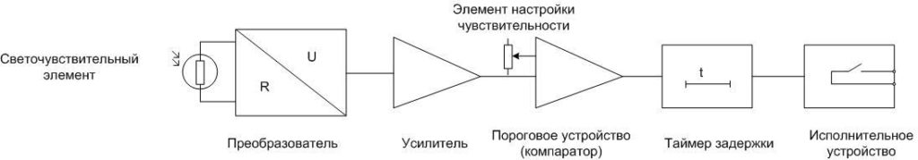
A device that is triggered when the illumination changes to a threshold value can be made on a different element base, but has approximately the same structure.
- As a photosensitive element, a semiconductor device can be used that changes its parameters or generates an EMF under the action of incident light. So, a photoresistor changes its resistance when irradiated with photons, a photodiode creates an EMF, etc. The light level sensor can be built into the device body or be remote.
- The converter transforms the variable into an electrical parameter that is convenient to work with. If a photoresistor is used as a photoelectric cell, then its resistance is converted into voltage.
- The amplifier amplifies the voltage to values at which the level of interference and interference becomes negligible.
- The threshold device compares the set voltage value with the voltage coming from the amplifier. If it becomes greater or less than the reference level, the comparator changes its state from one to zero or vice versa.
- Delay timer. Does not allow the relay to operate if the duration of the control signal is less than the specified one.
- executive device. When the state of the comparator changes, caused by the passage of illumination through a given threshold, it produces a control signal that can be used to control external devices. In most household appliances, this signal is the “dry contact” of the built-in electromagnetic relay. But there may be a discrete voltage from a solid state switch, a change in the state of an open collector transistor, etc.
Some nodes may be combined.So, the converter and amplifier are combined into one circuit. There may not be a delay timer in simple relays, but it has a useful function, which is discussed below. The element base can be different - analog or digital. But the principle of operation remains: comparison of the actual level of illumination with a given threshold and the issuance of a control signal.
Instrument selection criteria
To choose a photorelay, you need to consider several points:
- Supply voltage. It does not fundamentally affect consumer qualities, but it is convenient to power the device from the same voltage that is used for a controlled lighting device. It is even more convenient to have a dual-power photo relay - from a 220 volt network and from a low DC voltage.
- A construct for connecting a light sensor to a street lighting relay. The photocell can be built-in and remote. The first option is cheaper, the second is more convenient to install.
- The power of the output contact group. If it does not allow switching the existing load directly, you will have to connect it through an intermediate relay or magnetic starter.
- Degree of protection. Depends on the location of the intended installation of the main unit. If it is installed indoors, IP40 is sufficient. If outdoors, IP42 or IP44 will be required, and in some cases IP65.
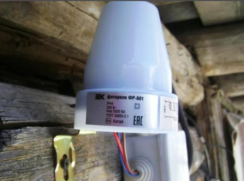
| photocell type | FR-601 | Euroautomatics F&F AZH | smartbuy | FR-05 |
| Load capacity, W | 1100 | 1300 | 2200 | 2200 |
Other characteristics (adjustment range of the turn-on delay, etc.) are selected based on local conditions and are not of a fundamental nature.
Device connection
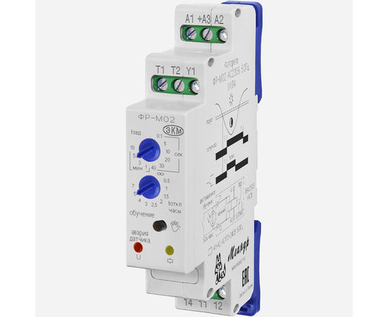
In many cases, the connection diagram for a particular relay, indicating the terminals, is applied directly to the device case.
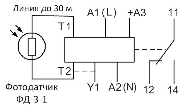
On the example of the FR-M01 relay, it can be seen that the following are connected to the relay:
- photosensor to terminals T1, T2:
- constant supply voltage of 24 volts to terminals A2, + A3 $;
- when powered from the mains, an alternating voltage of 220 V is supplied to A1, A2 (the device has a dual power supply circuit);
- terminals 11,12,14 are used for load control.
Other photo relays for street lighting have a similar connection scheme. It is only necessary to ensure that the load power does not exceed the load capacity of the output contacts. In this case, it is equal to 16 amperes at a switched voltage of 220 volts (not the supply voltage of the photorelay!) Or 30 volts DC. This is a fairly high load capacity, but if it is not enough or a low-power relay of a different type is used, a powerful load can be controlled through an intermediate relay or a magnetic starter.
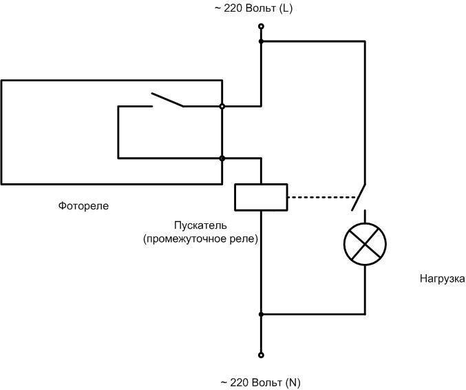
The principle is simple - the photo relay controls the starter, and the starter's powerful contacts switch the lamp, the electric motor of the irrigation pump, etc.
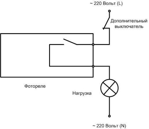
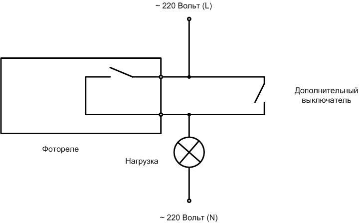
You can connect an additional switch and turn on the light regardless of the photo relay. Another scheme allows the lighting to be turned off even if the light control device gives the command to turn on.
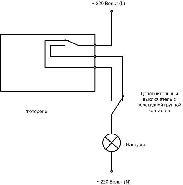
There is also a connection scheme for completely independent control, allowing the light to be turned on and off at will, regardless of the state of the relay. The problem is to purchase a household switch with a changeover contact.You can use an industrial switching element, but there is a question of aesthetics. The photo relay must also have a changeover type output contact.
Adjusting the photosensitive device
After connection, the level of operation of the photorelay must be adjusted. This is done experimentally. The minimum sensitivity is set - the regulator knob is turned to the extreme position, the lighting lamps should not be on (if they are on, then the highest sensitivity is set). Then you need to wait until the illumination drops to a level at which it is desirable to turn on the lighting devices. After that you need rotate the setting element in the direction of increasing sensitivity until the light turns on. The next day, it is necessary to check the moment of operation and, if necessary, adjust it more precisely. In the morning, the light will go out at about the same light level.
Important! In order to avoid multiple operations with a light flux close to the threshold, most devices have hysteresis - the on level is slightly lower than the off level. This must be taken into account when adjusting the device.
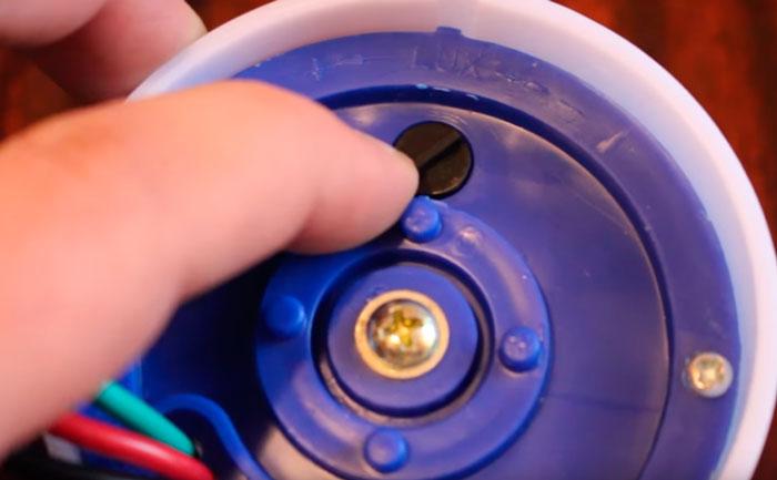
Advanced devices have a learning button. When the required illumination is reached using this function, the photo relay will remember the set level, and will continue to operate when the recorded threshold is reached.
If the relay has an adjustable delay timer, its operation time must also be selected experimentally in order to avoid turning on the light during a short-term increase in illumination. For example, when the headlights of passing cars hit the photosensor.
Video: A detailed review and setup of the Proxima PS-3 photo relay.
Errors when connecting and installing a photorelay
The connection diagram of the photorelay is quite simple. To avoid errors, simply check the installation. Problems in most cases are associated with incorrect installation of photo sensors.
Often, installers are carried away by looking for a convenient place for attaching a remote photocell and exceed the allowable cable length. To avoid this, before starting work, it is enough to carefully read the instructions.
The light sensor itself must be installed taking into account simple rules. Their non-observance can add problems instead of the comfort of lighting control:
- it is impossible to install a photoresistor so that light from artificial sources falls on it - illumination lamps of a neighboring area, etc., otherwise it will perceive such illumination as the onset of morning;
- on the contrary, it is impossible to install a photosensitive element in the shade zone at sunrise - this will cause a delay when turning on;
- The surface of the photo sensor must be protected from dust, precipitation, etc., and if this is not possible, the element must be regularly inspected and cleaned.
Video lesson: Wiring diagram and principle of operation Photorelay FR-602 from IEK.
The rules are simple, but it is much more convenient to follow them when using a relay with an external photocell. And the executive unit itself can be mounted where it is more convenient to connect it to the lighting control circuit - for example, in a power cabinet.