Features of connecting and controlling the addressable LED strip
The use of LEDs in lighting elements provides equipment designers with almost limitless possibilities. Until recently, consumers were fascinated by the capabilities of devices built on the basis of tri-color radiating elements (RGB). Today, new products have appeared, the potential of which seems to be unlimited.
Addressable LED strips
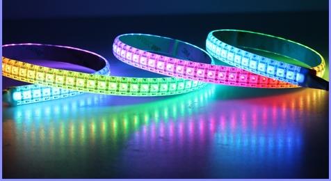
Such a lighting device has become an address LED strip. The brightness and ratio of basic colors, as in a conventional RGB lamp, are regulated by the method of pulse-width modulation, which is used in digital load control. The fundamental difference between the addressable device is that each light-emitting element is controlled separately (for a conventional tape, the entire segment of the web is equally lit).
Address tape device
Addressable LEDs became the basis for the construction of such lighting devices.They contain the actual semiconductor light emitting element and an individual PWM driver. Depending on the type of the address element, the RGB LED can be located inside a common housing or be taken out and connected to the driver outputs. Separate LEDs or an RGB assembly can be used as a light emitter. The supply voltage can also be different. Comparative characteristics of common microcircuits used to control colored LEDs are shown in the table.
| PWM driver | U supply, V | LED connection | Note | Current consumption |
| WS2811 | 12-24 | External | Built-in voltage regulator for 12 V. Fast and slow modes | Depending on the applied LED |
| WS2812B | 5 | built-in | Form factor LED - 5050 | Up to 60 mA per element (at maximum brightness) |
| WS2813 | 5 | built-in | Form factor LED - 5050 | Up to 60 mA per element (at maximum brightness) |
| WS2815 | 12 | built-in | Form factor LED - 5050 | Up to 60 mA per element (at maximum brightness) |
| WS2818 | 12/24 | External | The control input voltage is up to 9 V. Additional control input | Depending on the applied LED |
The current consumption of one meter by the address tape is quite large, because the power is spent not only on the glow of p-n junctions, but also on the switching losses of PWM drivers.
Lamp element device
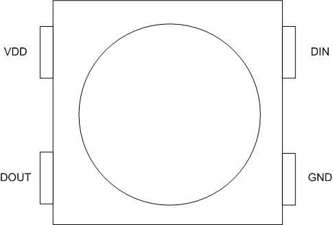
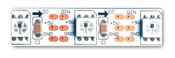
Each addressable LED contains a minimum number of pins:
- U power supply (VDD);
- common wire (GND);
- data input (DIN);
- data output (DOUT).
This allows elements with built-in emitters to be placed in 4-pin packages (WS2812B).
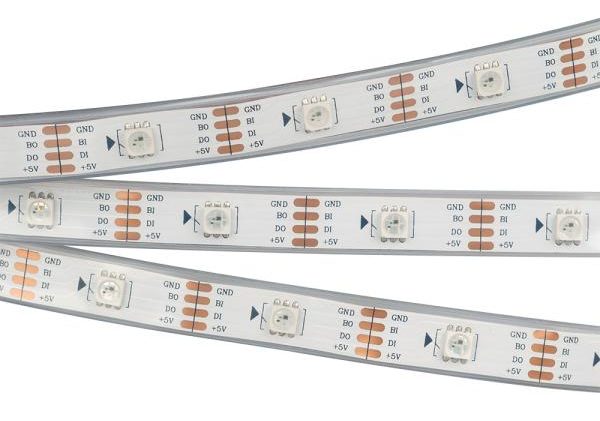
Chips with an external LED connection will require at least three more pins to connect the LEDs.As a result, the standard package with 8 pins has one free leg, which developers can use for other needs.
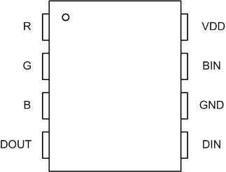
So, the designers of the WS2811 chip used a free pin for the speed switch, and WS2818 for the backup data input (BIN).
Connection of elements
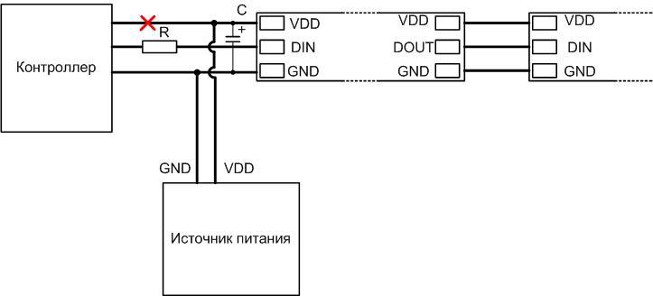
All elements located on the canvas are connected in parallel by power supply, and in series via the data bus. The control output of one microcircuit is connected to the input of another. The control signal from the controller is fed to the leftmost DIN output according to the driver circuit.
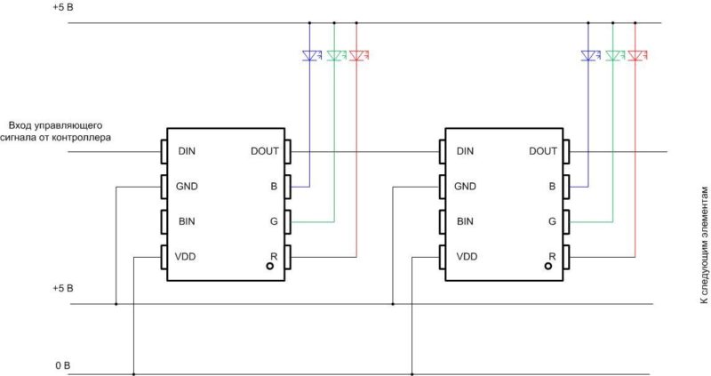
It is better to power the LEDs and microcircuits from a separate unit, especially if the tape is powered by a voltage other than 5 V. The common wire of the controller and the voltage source must be connected.
Glow control
The elements of the address tape are controlled via a serial bus. Typically, such buses are built on a two-wire circuit - a strobe line and a data line. There are also such tapes, but they are less common. And the described devices are controlled by a single-wire circuit. This made it possible to simplify the canvas, reduce its cost. But this is paid for by the low noise immunity of the LED device. Any induced interference with sufficient amplitude can be interpreted by the drivers as data and illuminate unpredictably. Therefore, during installation, additional measures must be taken to protect against interference.
The control protocol contains commands of 24 bits. Zero and one are encoded as pulses of the same frequency but different durations.Each element writes ("latches") its command, after a pause of a certain duration, the command for the next microcircuit is transmitted, and so on along the chain. After a longer pause, all elements are reset and the next series of commands is transmitted. The disadvantage of this principle of building a control bus is that the failure of one microcircuit interrupts the transmission of commands further along the chain. The latest generation drivers (WS2818, etc.) have an additional input (BIN) to avoid this problem.
"Running Fire"
Separate consideration deserves the so-called SPI-tape, which in everyday life is called "running fire" because of the most common lighting effect that is built on it. The difference between such a tape and the types considered is that the data bus contains two lines - for data and for clock pulses. For such devices, you can purchase a commercially manufactured controller with a set of effects, including the mentioned "running fire". You can also control the glow from conventional PIC or AVR controllers (including Arduino). Their advantage is increased noise immunity, and the disadvantage is the need to use two controller outputs. This can serve as a limitation for the construction of complex light systems. Also, such devices are characterized by a higher cost.
Luminaire connection diagram and typical errors
The scheme for switching on multimedia devices has much in common with the scheme of conventional RGB illuminators.But there are also differences - in order to correctly connect the addressable LED strip to the controller, you need to keep in mind a few points.
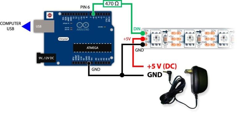
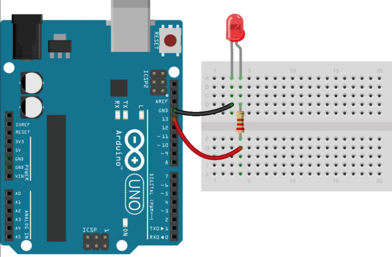
- Due to the increased power consumption of the address tape, it is impossible to power it from the Arduino board (if small segments are used, it is undesirable). In the general case, a separate source will be required for power supply (in some cases there may be one, but the power circuits for the LEDs and the controller must be made separately). But common the wires (GND) of the power circuits and the Arduino board must be connected. Otherwise, the system will be inoperable.
![Features of connecting and controlling the addressable LED strip]()
- Due to reduced noise immunity, the conductors connecting the controller output and the web input should be kept as short as possible. It is highly desirable that they be no longer than 10 cm. Also, it will not be superfluous to connect a capacitor C to the power line for a voltage exceeding the supply voltage of the tape, and with a capacity of 1000 microfarads. It is necessary to install the capacitor in the immediate vicinity of the tape, ideally on contact pads.
- Strips of tape can unite sequentially. The DOUT output must be connected to the DIN input of the next piece. But with a total length exceeding 1 meter, a serial connection cannot be used - the conductors of the web power lines are not designed for high current. And in this case, it is necessary to apply a parallel connection of the segments.
- If you connect the controller output and DIN input directly, if an abnormal situation occurs in the luminaire, the controller output may fail. To avoid this, a resistor with a resistance of up to several hundred ohms must be placed in the wire break.
Failure to follow these simple rules can lead to the inoperability of the multimedia system or to the failure of its components.
Checking the health of the address tape
Sometimes there is a need checks luminaire for performance. And here problems can arise, because it will not be possible to light the LEDs by supplying power to the tape. Also, it will not be possible to check the serviceability with a tester: the maximum possibilities in this case are to ring for the integrity of the power lines and interconnections. Therefore, the main way to detect the luminaire performance is to connect it to the controller.
If there is a canvas with a single-wire control bus, you can check the addressable LED strip by touching your finger to the contact pad to which the control signal is applied (when power is applied to the strip). This may cause one or more LEDs to light up.
Addressable LED-ribbon has multimedia capabilities an order of magnitude higher than other LED devices. You just need to understand the management and remember a few simple conditions so that there are no disappointments and senseless financial losses.