How to connect addressable LED strip WS2812B to Arduino
The development of lighting technology based on LEDs continues rapidly. Just yesterday, controller-controlled RGB ribbons, whose brightness and color can be adjusted using a remote control, seemed like a miracle. Today, lamps with even more features have appeared on the market.
LED strip based on WS2812B
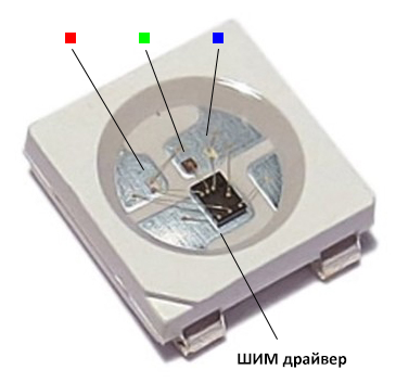
The difference between the addressable LED strip and the standard one RGB thing is brightness and color ratio of each element are adjusted separately. This allows you to get lighting effects that are fundamentally inaccessible to other types of lighting devices. The glow of the addressable LED strip is controlled in a known way - using pulse-width modulation. A feature of the system is to equip each LED with its own PWM controller. The WS2812B is a tri-color light emitting diode and a control circuit combined in a single package.
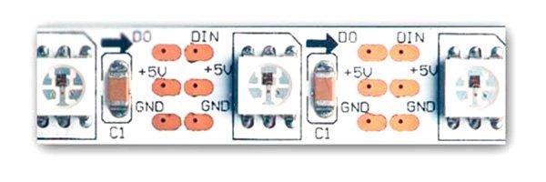
The elements are combined into a power tape in parallel, and are controlled via a serial bus - the output of the first element is connected to the control input of the second, etc. In most cases, serial buses are built on two lines, one of which transmits strobes (clock pulses), and the other - data.
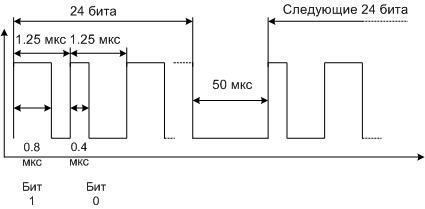
The control bus of the WS2812B chip consists of one line - data is transmitted through it. The data is encoded as pulses of constant frequency, but with different duty cycles. One pulse - one bit. The duration of each bit is 1.25 µs, the zero bit consists of a high level with a duration of 0.4 µs and a low level of 0.85 µs. The unit looks like a high level for 0.8 µs and a low level for 0.45 µs. A 24-bit (3-byte) packet is sent to each LED, followed by a low-level pause for 50 µs. This means that data will be transmitted for the next LED, and so on for all elements of the chain. The data transfer ends with a pause of 100 µs. This indicates that the tape programming cycle is complete and the next set of data packets can be sent.
Such a protocol makes it possible to get by with one line for data transmission, but requires accuracy in maintaining time intervals. The discrepancy is allowed no more than 150 ns. In addition, the noise immunity of such a bus is very low. Any interference of sufficient amplitude can be perceived by the controller as data. This imposes restrictions on the length of conductors from the control circuit. On the other hand, this makes it possible ribbon health check without additional devices.If you apply power to the lamp and touch the contact pad of the control bus with your finger, some LEDs may randomly light up and go out.
Specifications of WS2812B elements
To create lighting systems based on the address tape, you need to know the important parameters of light emitting elements.
| LED dimensions | 5x5mm |
| PWM modulation frequency | 400 Hz |
| Current consumption at maximum brightness | 60 mA per cell |
| Supply voltage | 5 volts |
Arduino and WS2812B
The Arduino platform, popular in the world, allows you to create sketches (programs) for managing address tapes. The capabilities of the system are wide enough, but if they are no longer enough at some level, the acquired skills will be enough to painlessly switch to C ++ or even to assembler. Although the initial knowledge is easier to get on the Arduino.
Connecting WS2812B Ribbon to Arduino Uno (Nano)
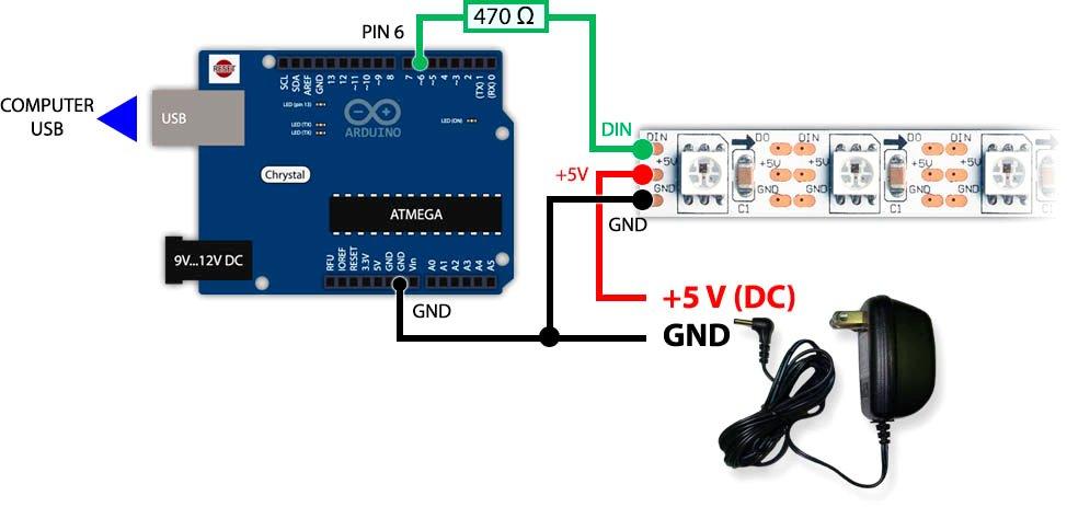
At the first stage, simple Arduino Uno or Arduino Nano boards are enough. In the future, more complex boards can be used to build more complex systems. When physically connecting the addressable LED strip to the Arduino board, several conditions must be observed:
- due to low noise immunity, the connecting conductors of the data line should be as short as possible (you should try to make them within 10 cm);
- you need to connect the data conductor to the free digital output of the Arduino board - it will then be specified programmatically;
- due to high power consumption, it is not necessary to power the tape from the board - separate power supplies are provided for this purpose.
The common power wire of the lamp and Arduino must be connected.
WS2812B Program Control Basics
It has already been mentioned that in order to control the WS2812B microcircuits, it is necessary to generate pulses with a certain length, maintaining high accuracy. There are commands in the Arduino language for the formation of short pulses delayMicroseconds and micros. The problem is that the resolution of these commands is 4 microseconds. That is, it will not work to form time delays with a given accuracy. It is necessary to switch to C ++ or Assembler tools. And you can organize the control of the addressable LED strip through Arduino using libraries specially created for this. You can start your acquaintance with the Blink program, which makes the light-emitting elements blink.
fast led
This library is universal. In addition to the address tape, it supports a variety of devices, including tapes controlled by the SPI interface. It has wide possibilities.
First, the library must be included. This is done before the setup block, and the line looks like this:
#include <FastLED.h>
The next step is to create an array to store the colors of each light emitting diode. It will have the name strip and dimension 15 - by the number of elements (it is better to assign a constant to this parameter).
CRGB strip[15]
In the setup block, you need to specify which tape the sketch will work with:
void setup() {
FastLED.addLeds< WS2812B, 7, RGB>(strip, 15);
intg;
}
The RGB parameter sets the color sequence order, 15 means the number of LEDs, 7 is the number of the output assigned for control (it is also better to assign a constant to the last parameter).
The loop block begins with a loop that sequentially writes to each section of the array Red (red glow):
for (g=0; g< 15; g++)
{strip[g]=CRGB::Red;}
Next, the formed array is sent to the lamp:
FastLED.show();
Delay 1000 milliseconds (second):
delay(1000);
Then you can turn off all elements in the same way by writing black in them.
for (int g=0; g< 15; g++)
{strip[g]=CRGB::Black;}
FastLED.show();
delay(1000);

After compiling and uploading the sketch, the tape will flash with a period of 2 seconds. If you need to manage each color component separately, then instead of the line {strip[g]=CRGB::Red;} several lines are used:
{
strip[g].r=100;// set the glow level of the red element
strip[g].g=11;// same for green
strip[g].b=250;// same for blue
}
NeoPixel
This library only works with NeoPixel Ring LED rings, but it is less resource intensive and contains only the essentials. In Arduino language, the program looks like this:
#include <Adafruit_NeoPixel.h>
As in the previous case, the library is connected, and the lenta object is declared:
Adafruit_NeoPixel lenta=Adafruit_NeoPixel(15, 6);// where 15 is the number of elements and 6 is the assigned output
In the setup block, the tape is initialized:
void setup() {
lenta.begin()
}
In the loop block, all elements are highlighted in red, the variable is passed to the feed, and a delay of 1 second is created:
for (int y=0; y<15; y++)// 15 - the number of elements in the lamp
{lenta.setPixelColor(y, lenta.Color(255,0,0))};
tape.show();
delay(1000);
The glow stops with a black record:
for (int y=0; y< 15; y++)
{ lenta.setPixelColor(y, lenta.Color(0,0,0))};
tape.show();
delay(1000);

Video tutorial: Samples of visual effects using address tapes.
Once you've learned how to flash the LEDs, you can continue learning how to create color effects, including the popular Rainbow and Aurora Borealis with smooth transitions. Addressable LEDs WS2812B and Arduino provide almost limitless possibilities for this.