DRL voltage regulation
In recent years, motorists have begun to equip their cars with daytime running lights. Although the rules allow the use of standard lighting devices (foglights, headlights, etc.) in this capacity, many prefer to perform DRLs in the form of separate units. And some motorists are faced with the fact that the LEDs, on the basis of which the lights are made, fail without having worked for a year. The reason for such a short service has not been clarified in detail. Perhaps this is due to the quality of LEDs from unknown manufacturers, or the fact that manufacturers greatly overestimate the declared resource of semiconductor products, or maybe it's all about insufficient cooling.
But there is a strong opinion that LEDs fail due to unstable voltage in the car's on-board network or due to short-term surges in the power circuit, the amplitude of which reaches several tens of volts. They are trying to escape from this trouble by installing a voltage stabilizer for the on-board network for the car's DRL.
How many volts should the stabilizer be
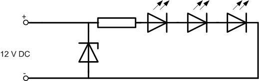
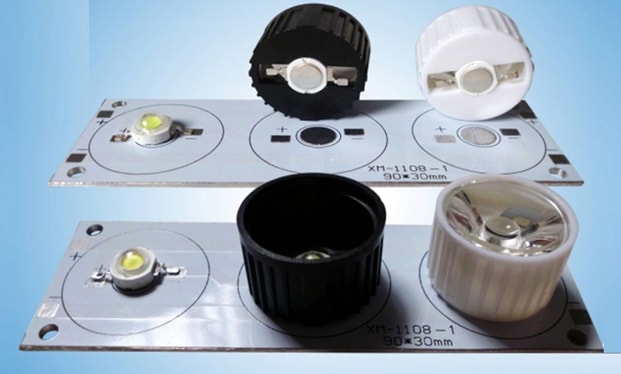
If the stabilizer DRL used with industrial lamps, its output voltage must be equal to the supply voltage indicated on the device case. In most cases it is 12 volts. For a homemade system, you need to consider its scheme.
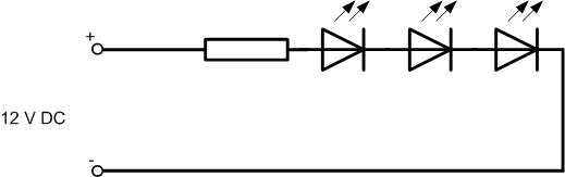
It usually consists of consistent chains of 2..4 LEDs and a quenching resistor. For normal operation of the LED, its nominal voltage must drop across it. For example, for an ARPL-Star-3W-BCB LED, the voltage drop is 3.6 V. For a chain of three elements, 3.6 * 3 = 10.8 volts must be provided. Another small voltage should drop on the ballast (its value is determined during the calculation, 1..2 volts). As a result, we go out to about 12 volts.
| LED type | Power, W | Voltage drop, V |
| TDS-P003L4U13 | 3 | 3,6 |
| TDSP005L8011 | 5 | 6,5 |
| ARPL-Star-3W-BCB | 3 | 3..3,6 |
| STAR 3WR | 3 | 3,6 |
| High Power 3W | 3 | 3,35..3,6 |
What are voltage stabilizers for DRL
The simplest and most inexpensive stabilizers are of the linear type. They redistribute the mains voltage between the regulating element (transistor) and the load.
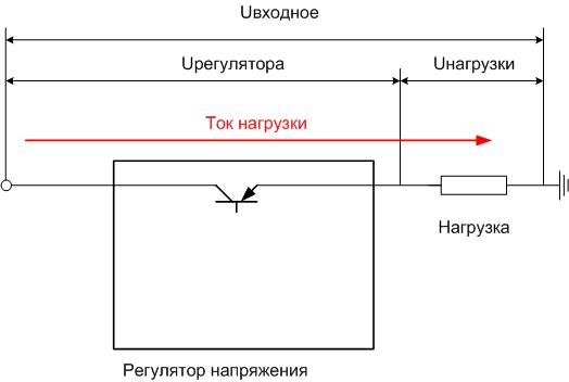
When the input voltage decreases or the load current increases, the transistor opens slightly, and the voltage across the load increases. If the input voltage has increased or the load current has fallen, the regulator closes the power element a little, and the voltage across the load decreases. This is how stability is achieved. Advantages of such stabilizers:
- simplicity;
- low cost;
- can be purchased in an integrated version for a fixed voltage.
Among the minuses are large power losses due to dissipation on the control element (in this regard, an effective heat sink is needed) and the need for a noticeable excess of the input voltage over the output.
Switching stabilizers are free from these shortcomings, they distribute energy over time, but their problem is the complexity of manufacturing. Self-assembly requires certain knowledge and qualifications.
How to choose the right
To select an industrial device, you must specify the following parameters:
- output voltage;
- operating current;
- minimum input voltage (the maximum is usually several tens of volts, such a voltage does not exist in the car network).
How to select the output voltage, said above. The operating current must exceed the current consumption of the lamps (or lamp, if the stabilizer is placed on each device separately) with a margin. Few people pay attention to the last parameter, but it can have a critical impact on the operation of the entire system.
Read also: How to choose the right running lights on a car so that you don’t get fined
We study popular voltage stabilizer circuits
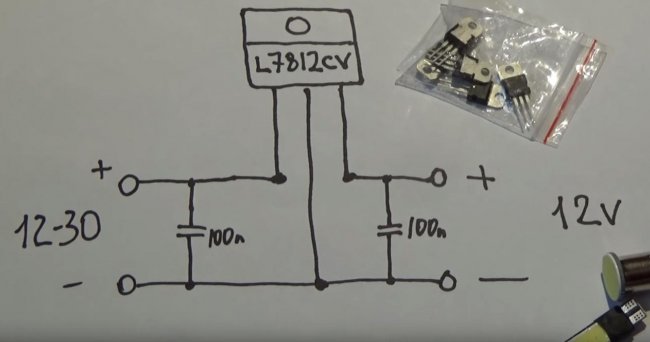
First of all, you need to choose a device scheme. There are many recommendations in the global network to assemble such blocks on integral linear stabilizers 7812 (KR142EN8B).
Those who publish such schemes pay attention to their simplicity and lack of need for customization, completely forgetting about one problem. For normal operation, at least 2.5 volts should fall on such a stabilizer - this is written in any datasheet.Simply, for at least some effective stabilization at the output, there must be at least 14.5 volts at the input. In a car with a working generator, this voltage should not be, and at a lower value, it makes no sense to use such a circuit. As a compromise, you can use a nine-volt stabilizer (LM7809), its performance will start from 11.5 volts at the input, but the brightness of the lights will drop. According to the requirements of GOST, the minimum luminous intensity should be 400 cd, and you cannot fall below this limit..
Recommendations to put a diode at the input look even more thoughtless.
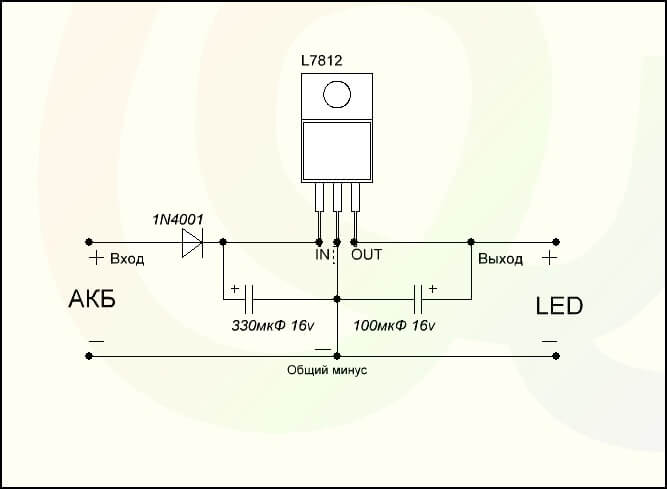
Its purpose is very doubtful - it is not necessary to protect the microcircuit from reverse polarity with a stable installation. But on the silicon p-n junction, an additional 0.6 volts will drop, and at least 15 volts will be needed for normal operation.
12 volt integrated-line circuits (with or without a diode) are suitable only for cutting off high-voltage spikes on the +12 volt bus (if any are actually present). That is, they can serve as a kind of "Zener barrier", but such a barrier can be made much simpler. It is necessary to turn on the zener diode Ust in parallel with the chain of LEDs, slightly exceeding the operating voltage. In normal mode, its resistance is large, it will not affect the operation of the lighting fixture. If the stabilization voltage is exceeded (for example, 15 volts), it will open and “cut off” the excess.
Stabilizers on LDO (low drop out) microcircuits work a little better.They look like regular linear regulators, but they only need a 1.2 volt drop to function properly, and effective regulation will begin as early as 13.2 volts. Which is already better, but still not enough for normal functioning. To work in such a circuit, the LM1084 and LM1085 microcircuits are suitable, but the circuit for switching them on is somewhat more complicated.
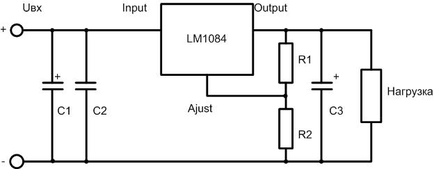
To obtain an output voltage of 12 volts, the resistance of the resistor R1 must be 240 ohms, and R2 - 2.2 kOhm. There is a fundamental obstacle to further reducing the drop - the regulator is made on a bipolar transistor, and at least 1.2 volts should fall on its emitter and collector junctions. This is easily circumvented by using a field effect transistor as a regulating element. Integrated circuits built according to this principle are difficult to find, even more difficult to select according to the required parameters, and they are more expensive. But to make such a device yourself on discrete elements is within the power of even a radio amateur of average qualification.
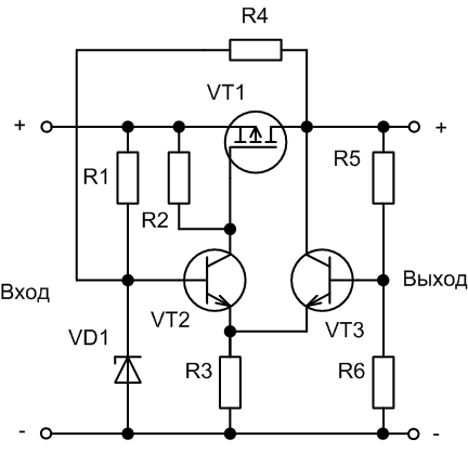
Element ratings:
- R1 - 68 kOhm;
- R2 - 10 kOhm;
- R3 - 1 kOhm;
- R4, R5 - 4.7 kOhm;
- R6 - 25 kOhm;
- VD1 - BZX84C6V2L;
- VT1 - AO3401;
- VT2, VT3 - 2N5550.
The output voltage is set by the ratio R5/R6. With the indicated ratings, the output will be 12 volts, the input will need no more than 12.5. This is a major improvement. But a fundamental leap can only be achieved by using a switching power supply. Such a step-up converter can be assembled on the XL6009 chip.
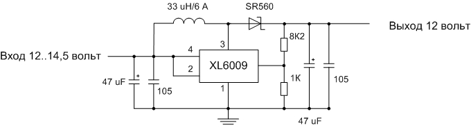
Such a stabilizer in finished form can be ordered on popular Internet sites.But there is a problem - out of economy, manufacturers often install elements designed for a current of no more than 1 A (although the microcircuit is capable of delivering current up to 3 A). Or, for example, input or output oxide capacitors may not be installed. Even the Schottky diode N5824, indicated in the datasheet, starts to heat up at currents above 1.5 A. Instead, you need to use a more powerful diode, such as SR560. All these replacements and simplifications lead to overheating of the board and its failure.
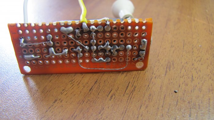
The video shows an example of assembling a 12 volt stabilizer.
Manufacturing Recommendations
For manufacturing, electronic components for the selected circuit will be required. You can buy them in specialized stores or via the Internet. For a device based on an integrated linear stabilizer, a case is not needed, but you need to take care of the radiator. Also, a radiator will be needed in the manufacture of a linear on discrete elements. More complex devices must be assembled on boards. Those who own home technologies will be able to design and etch a printed circuit board on their own. The rest is better to use a breadboard - cut off the necessary piece and mount the elements on it.
You also need to pick up or assemble a case, not forgetting about heat dissipation. Tightening the board into heat shrink is not the best option in this regard. You will also need a soldering iron with a set of consumables.
It is difficult to give general instructions for manufacturing - it all depends on the chosen scheme and preferred technologies. But you can give some advice to those who have little experience in the manufacture of electronic devices:
- all connections must be carefully soldered (trying not to overheat the elements and conductors in insulation) - operating conditions will be associated with shaking and temperature changes, and poor-quality soldering will immediately make itself felt;
- the body of the structure must prevent water and dirt from getting inside - when installing the device under the hood, these substances will be enough;
- if the case is not used, the soldering points must be carefully isolated - for the same reasons;
- after assembling and checking the performance, it will not be superfluous to cover the board from the soldering side with varnish and dry it.
Only a careful approach to manufacturing can guarantee at least some long work of homemade products in harsh conditions.
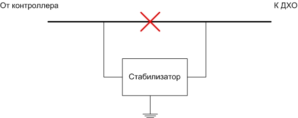
Installation on DRL
The stabilizer, regardless of how it is assembled, is installed in a break in the wire coming from the switch or controller to the daytime running lights. This is done in any convenient place. If the power of the regulator is sufficient to work with two lamps, you can include it in the break of the power wire of two lamps, up to the point of separation. If not, each DRL lamp will require two devices.
We must not forget to connect the negative wire to the common conductor of the car. Another frequently asked question is the installation of a heatsink for a linear regulator. There is an idea to use a car body as a cooling element. Its area is large, and it will perfectly remove heat. Provided that reliable thermal contact between the surface of the microcircuit and the surface of the body is provided. And this will require, at a minimum, the removal of the paintwork at the installation site, as well as drilling a hole for the fastening screw.In this place, a center of corrosion quickly forms. Therefore, this idea is not the best. It is better to make a small separate radiator from a piece of aluminum sheet.
Video: Connecting and checking stabilizers L7812CV and LM317T for LED DRLs on the VAZ-2106.
The question of using a stabilizer for daytime running lights is not as simple as it seems at first glance. To decide on its application and the choice of installation method, a certain technical background is required. Review materials will help to make this choice.