Making a DRL controller
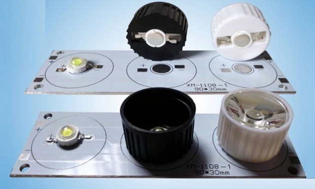
The rules of the road require that the car be equipped with daytime running lights (DRL, foreign designation - DRL) in the daytime. Not every car has them provided for by the design, so the role of DRL is often performed by the lights included in the standard equipment of the car - fog lights, low beam headlights, etc. Some motorists install homemade DRLs on vehicles. To control them, a separate device is required - the controller.
What is a DRL controller
Controller DRL - an electronic system that controls the glow of the DRL. Its functions may include:
- automatic inclusion of daytime running lights - the main and mandatory service;
- turning the DRL on and off depending on the voltage in the car's on-board network;
- smooth voltage supply to DRLs - if they use incandescent dumps, this can increase their service life;
- DRL brightness adjustment (manual or automatic).
Other service functions are also possible - everything is limited only by the imagination of the developers.
Manufacturing instructions
The daytime running light control unit can be purchased. And you can make your own. Several schemes of various DRL control units are offered - depending on the availability of the element base and the qualifications of the master, you can choose the best option.
DRL controller based on relay
The simplest DRL controller can be assembled on a single relay. True, it will perform only basic functions:
- inclusion of DRL when the ignition is turned on;
- turning off the lights when the starter is running;
- turning off the DRL when turning on the dipped / main beam headlights, dimensions, fog lights (may require a slight complication).
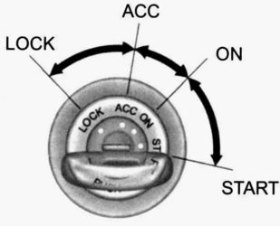
The operation of the controller is tied to the position of the ACC key (accessories) in the ignition locks of many cars, designed to turn on auxiliary equipment (car audio, cigarette lighter, etc.). The lock has a separate output (a large wire is connected to it), it has voltage when the ignition is turned on, but is absent when the starter is turned on. This algorithm correlates well with the conditions for turning on the DRL, so it is convenient to use this wire to turn on the DRL.
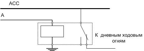
When voltage appears on wire A, the relay is activated, the contacts open and the DRL goes out. The connection of this conductor depends on the electrical circuit of the car. Voltage can be selected as a damping signal:
- turning on foglights;
- near or far beam;
- dimensions.
If the circuit of the car's lighting equipment is built in such a way that a separate wire goes to standard lighting (which then branches), then you can use it. If this is not possible, then there are two options:
- use only one signal to extinguish DRL (only high beam, only fog lights, etc.);
- combine all the necessary signals using diodes (according to the OR scheme).
In the latter case, the circuit will become a little more complicated - it will take several diodes according to the number of signals by which the DRL should go out.
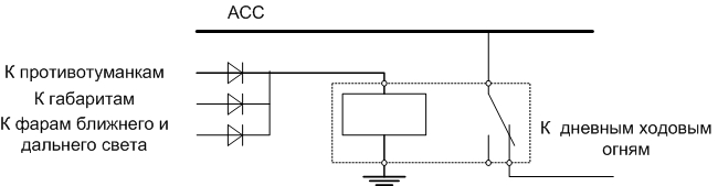
In this scheme, the inclusion of any of the specified lighting equipment will cause the relay to operate, open the contacts, de-energize the DRL.
Important! The use of diodes for decoupling circuits is mandatory. In their absence, turning on one piece of equipment will turn on the rest of the lights.
The specific connection points will vary from vehicle to vehicle depending on the layout and topology of the onboard network. A separate housing to accommodate this version of the DRL control unit is not needed. The relay can be placed in any convenient place. If diodes are needed, they can be soldered directly to the output of the relay coil.
On the comparator
On the Internet, you can find a controller circuit on a comparator. Its work is based on the control of the voltage of the onboard network. When powered by a battery, it is about 12 volts, and with the engine running and powered by a generator, about 13.5 volts. When the voltage passes through the threshold, the comparator through the power switch will turn on or off the lighting devices. The turn-on level is set by a tuning resistor.
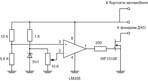
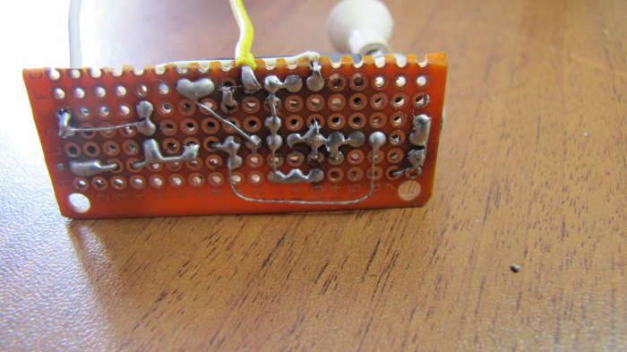
The problem here is that the DRL should not turn on when the engine is running, but when the ignition is turned on. And this moment is not tracked in this scheme. But if someone wants to assemble it, then you can make it in the form of a module. Electronic components and a connector for connection must be placed on the board and put it all in the case. Preferably metal. Those who own home PCB manufacturing technologies (LUT, photoresist) can design and etch the board. Others can assemble the circuit on a piece of breadboard. The unit is installed in a convenient place and connected according to the diagram.
Using ATmega8 board
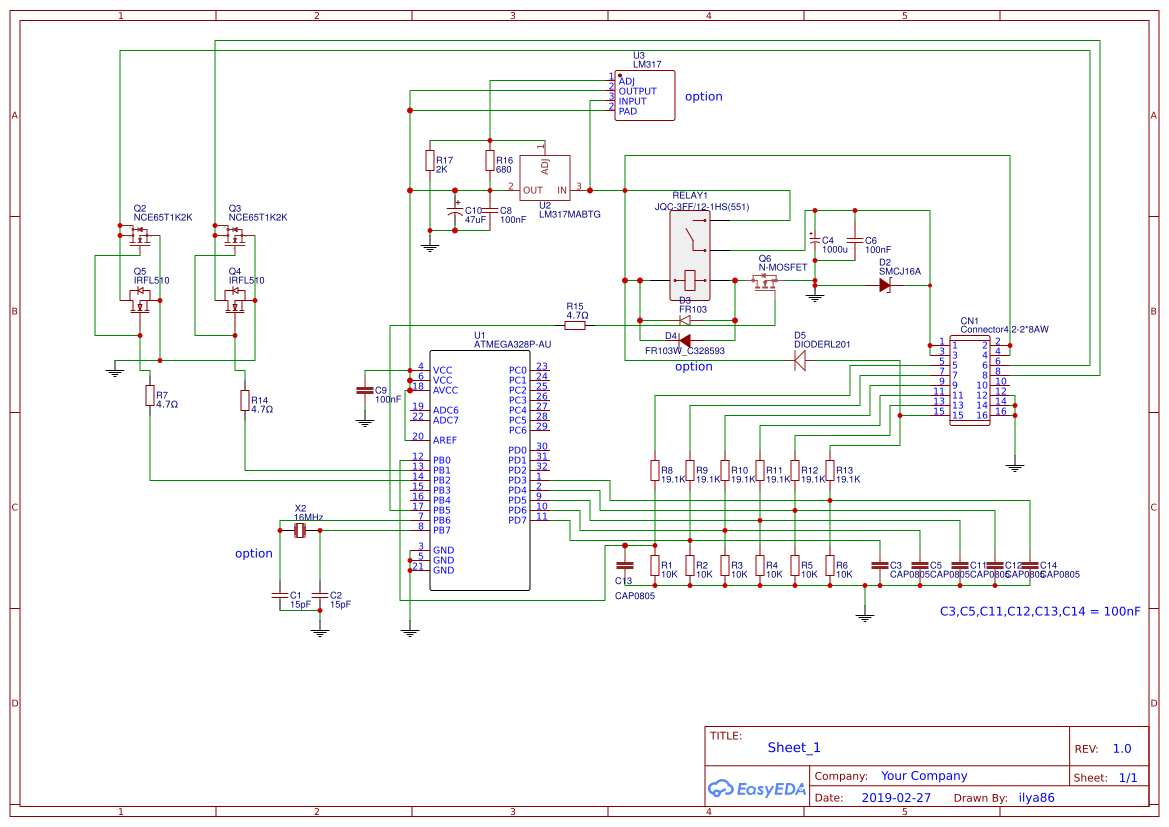
Many motorists themselves develop controller circuits for their own needs and post materials on the Internet. Here is one of the options on the popular ATmega8 microcontroller. Its use allows you to greatly expand the functionality of the control circuit.
When the ignition is turned on, power is supplied to the board and the controller waits for the engine to start. When a start signal is received, the control circuit checks the operation of one of the turn signals. If at least one direction indicator is on, the daytime running light on the corresponding side is dimmed. The level of illumination is regulated by the method of pulse-width modulation. The inclusion of low beam is also controlled, the presence of this signal also serves as a reason to turn off the DRL. The inclusion of foglights indicates bad weather conditions, so the brightness of the DRL, on the contrary, becomes maximum when the low beam is on. If emergency lights are on, then DRLs flash in antiphase with them. There is also a very useful feature - if the ignition is switched off and the dipped beam remains on, the running lights start flashing, reminding you that the battery may be exhausted.
In this case, the controller also does not turn on the lights when the ignition is on, but waits for the engine to start. But this shortcoming is easy to eliminate programmatically (you can contact the developer with such a request). Connection and assignment of board contacts to external circuits is given in the table.
| contact number | designation | Function |
|---|---|---|
| 1,3 | LED+ | DRL power line (output) |
| 2,4 | VCC | Power board |
| 6 | Lled | left light |
| 8 | led | right light |
| 5 | lbm | dipped beam |
| 7 | fog | Fog lights |
| 9 | Rin | Right turn signal |
| 11 | Run | Generator signal |
| 13 | Lin | Left turn signal |
| 15 | Ign | Ignition |
| 12,14,16 | GND | common wire |
You can download firmware for ATMega. It is better to assemble the controller on a printed circuit board, and the use smd-elements will significantly reduce the size of the module. This design is intended for qualified specialists, so it will not be difficult for them to design and manufacture a printed circuit board. Also on the global network you can find many other amateur designs for controlling DRL on other microcontrollers, including the popular "baby" ATTiny13. The functionality of the devices depends on the capabilities of the microcircuit and the imagination of the developer.
What is needed to make
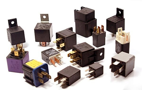
To make a simple DRL controller with your own hands, you will need a relay. You can use any 12 volt automotive relay with a normally closed or changeover group of contacts. The advantage of such a relay is a closed design.The case protects the insides well from external factors (water, dirt), so no additional measures are needed, and the relay can be installed in any convenient place. When using another relay (and you can use any model for a suitable voltage with the appropriate contact group), additional protection measures must be taken.
Diodes can be used any of the 1N400X series or others suitable in size. Almost any semiconductor device will pass by voltage, by current - so that it is enough to trigger the relay.

For more complex circuits, you will need the electronic components indicated in the diagrams (any operational amplifier suitable for the supply voltage can be used as a comparator), as well as an assembly board. To flash the microcontroller, you will need a programmer.
How to properly install the controller on the car
First of all, you need to find a diagram of the electrical equipment of the car and carefully understand it. It is necessary to determine to which circuits a home-made controller should be connected. Next, you should determine at what points it is more convenient to connect (not all circuits are easily accessible, to access some you will have to disassemble part of the machine's structure, remove panels, etc.).
Read also: How to choose the right running lights on a car so that you don’t get fined
The next step is to determine the wiring routes from the connection points to the controller terminals. It is difficult to give specific advice here - the layout and design of the electrical equipment of various cars can vary greatly.When this issue is completely clear, you can choose the optimal location for installing the controller board. It must be protected as much as possible from the high temperature of the running engine, from the ingress of water or dirt. The latter factor can be eliminated by placing the controller board in a case, but the case should not interfere with the cooling of electronic switch transistors. Therefore, a nice-looking option to tighten the board into heat shrink is not a good idea.
The power circuit that goes to power the DRL must be provided with a fuse for the appropriate current, regardless of the version of the controller.
Recommended: Video assembly of a simple DRL controller (DRL CONTROLLER).
If you decide to make the DRL controller yourself, you should immediately realize that the manufacturing and installation process is creative. Ready-made tips are not easy to find due to the difference in the design of the machine. You have to be prepared to make technical decisions. If this does not scare you, you can proceed to the selection of the circuit and the manufacture of the device.