The procedure for connecting a pulse light switch
The issues of saving electricity have not become less relevant since the advent of commercial power generation. From the first years of the use of electric lighting, the ideas of manual and automatic control of switching on consumers for the required period and switching off for the period of non-use have arisen. One of the elements of such systems is an impulse relay.
Purpose, principle of operation and application
A classic impulse relay, like a conventional one, consists of a coil with a core, a movable system and a contact group. Such a device is often called bistable - because it has two stable states: with the contacts turned off and with the contacts turned on. The state of the relay is maintained when de-energized, and this is the main difference from the traditional system.
In real structures, the long-term presence of voltage on the coil is considered unnecessary and even harmful - the winding can overheat. Therefore, such a device is controlled by short pulses:
- the first pulse closes the contacts;
- the second opens;
- the third closes again and so on.
Each pulse flips the contacts to the opposite state. Pulses are generated by switches. It is logical to make the switching device in the form of a button without fixing in the pressed position.
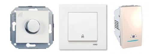
The usual keyboard apparatus is of little use here - it is easy to forget it in the on position, and after a while the coil will fail. Buttons for doorbells can be used instead of switches.
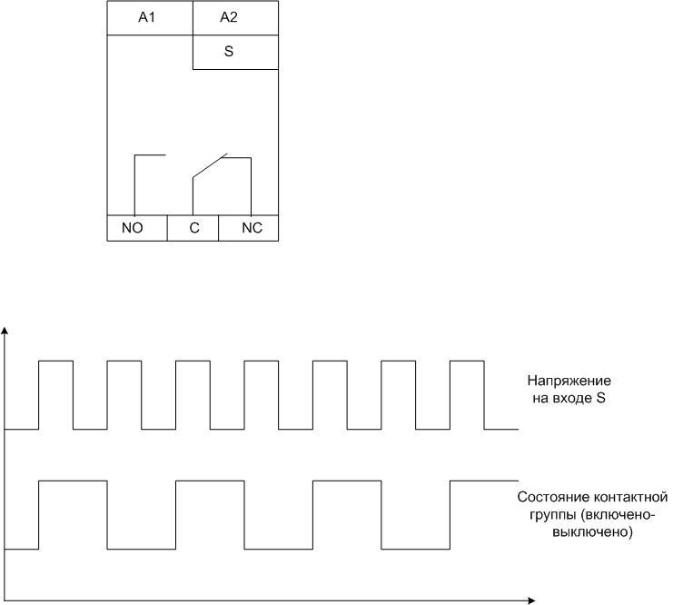
A typical relay has inputs:
- A1 and A2 - for connecting 220 volt power;
- S – control input;
- NO, C, NC - contact system terminals.
There is no single standard for marking terminals. Input markings may vary from manufacturer to manufacturer.
In fact, switching does not occur synchronously by pressing a button - the system waits for the next transition of the sinusoid through zero. This is done so that the switching current is zero, which prolongs the life of the contact group. But such a transition occurs twice per period, the maximum delay is 0.01 seconds, so a short pause is not noticeable.
Many impulse relays for electric lighting control have additional enable and disable inputs. They have priority over the S input - when energized, the relay can be forced on or off, regardless of the state on the S terminal.
An impulse switch can be used to create lighting control systems in which the light can be turned on and off from several places independently of other switching devices.Classically, such circuits are built on through and cross switches, but the use of pulse switching devices has its advantages.
Main technical characteristics
When purchasing a device, you need to pay attention to the main parameters:
- power of the contact group;
- supply voltage;
- coil operation current;
- execution of the contact group (closing-opening or changeover);
- additional service features.
You also need to pay attention to such an (illogical at first glance) parameter as the number of connected switches. It would seem that the characteristic is absurd, but one must take into account the widespread use of devices with backlight chains. If there are a lot of them, then the prevailing total current through these circuits will be enough to operate the relay.
The control voltage for most devices is 220 volts, but there are also relays with low voltage control (12..36 volts). Such devices have a huge safety advantage, but require an additional power source. Therefore, in everyday life (unlike in production), such devices are not widely used.
In the control circuit, bistable switching devices consume a very small current (this power consumption practically does not affect the readings of the electric meter). This fact makes it tempting to make control circuits with wires of reduced cross section (up to 0.5 sq. mm). It should be remembered that in order to protect such conductors, it will be necessary to install a separate machine in the switchboard with a lower trip current. Appropriateness is decided on a case-by-case basis.
Varieties of impulse relays, their disadvantages and advantages
Bistable switches can be produced in two versions:
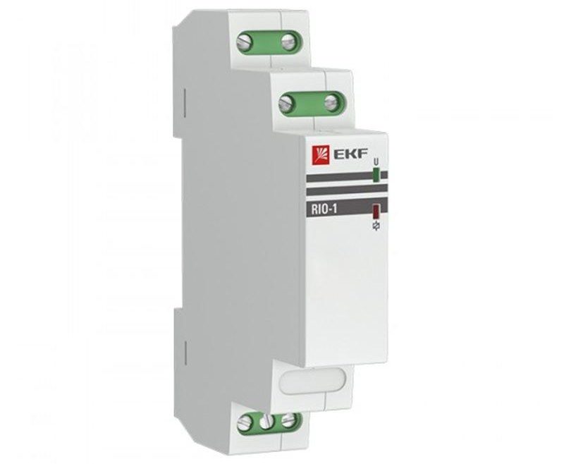
- classic electromechanical (available in a housing for mounting on a standard DIN rail);
- modern electronic.
The second option allows you to reduce the dimensions, increase the reliability of the device, and also allows developers to implement almost unlimited service functions (off-delay timers, control over WI-Fi, etc.). The disadvantages of pulsed electronic light switches include low noise immunity.
classic electromechanical relay is insensitive to interference and pickups, but it is noisy - constant loud clatter can be annoying.
Various impulse relay connection schemes
The simplest scheme of the lighting system on a bistable device looks like this:
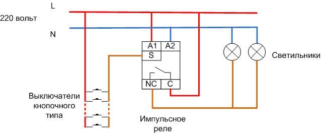
If the switches are not backlit, then their number can be infinite. In fact, there is a limitation on the installation range - with a certain cable length, the resistance of the conductors can limit the current required to turn on the relay. But for reasonable distances, this limitation is theoretical. Quantity parallel connected lamps is limited by the load capacity of the output contact group.
| Relay name | Type of | Load capacity of contacts, A |
| MRP-2-1 | electromagnetic | 8 |
| MRP-1 | electromagnetic | 16 |
| BIS-410 | Electronic | 16 |
| RIO-1M | electromagnetic | 16 |
| BIS-410 | Electronic | 16 |
The table shows that many relays allow a load of 1760 to 3520 watts. This is enough to cover almost all reasonable lighting needs (especially considering the spread of LED equipment) without the use of intermediate relays.
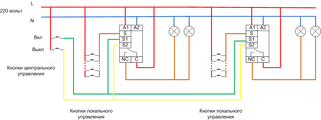
Another variant of the circuit is using priority inputs for enabling or disabling.This principle is used when it is necessary to provide centralized control of the lighting of several rooms or zones. When manipulating the central control buttons, the state of the lamps will not depend on the previous position - all lamps can be turned on or off at the same time. Such a two-channel switching allows you to turn on or off the light in all rooms at once from one place, and then control the light from local buttons.
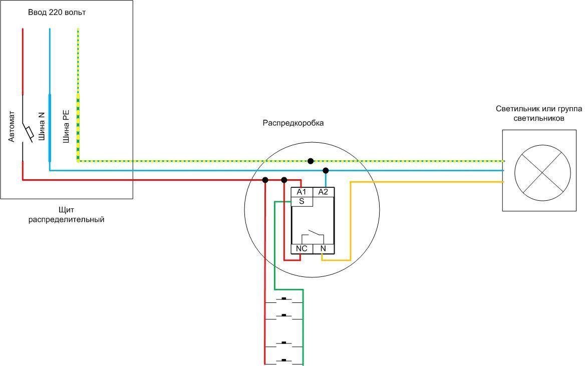
Installation of an electromechanical pulse device is carried out in a switchboard - it is most convenient to mount a DIN rail there. The topology of laying cable products is considered using a simple diagram as an example, and it looks like this:
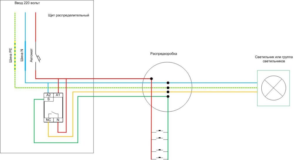
Some of the connections are made by wires in the switchboard. You will also need:
- five-core cable for laying from the shield to the junction box (in the absence of a PE conductor - four-core);
- three-core to the luminaire or group (two-core if there is no PE);
- push-button switches are connected by a loop with a two-wire cable.
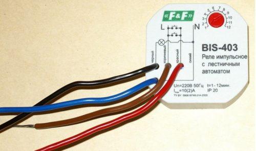
If an electronic relay is used, it can be installed in a junction box. Then the cables are laid like this:
The difference from the previous version is that some of the connections are made in the distribution box, and there is also no need to lead the circuit from the switches back to the switchboard. The number of cores in the cable from the box to the shield is reduced: in the absence of a PE conductor, two wires are enough. Therefore, such a scheme is generally more justified economically.
To consolidate information on connecting, we recommend a video.
Impulse relay or cross switch
A control scheme of three or more places can also be organized using two checkpoints and several (according to the number of required posts) cross devices.
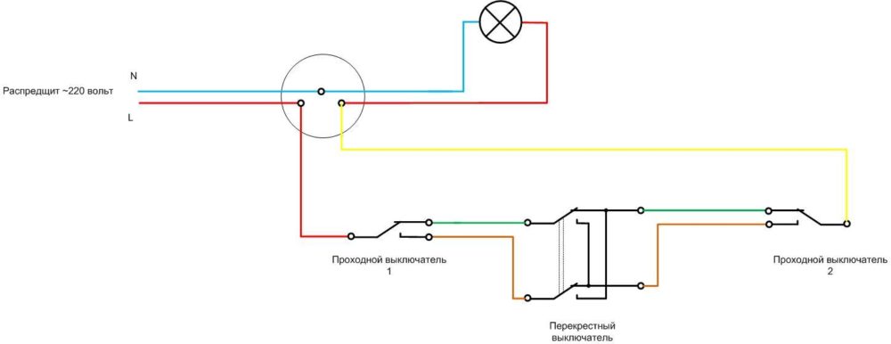
The cabling in this case looks like this (PE conductor not shown). Obviously, in this case, all the switches are connected to each other by a cable of three wires against two.
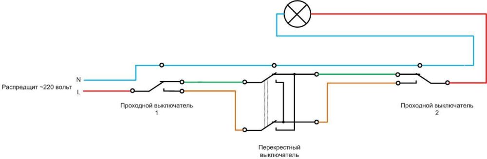
You can do without a junction box and make connections with a loop. In this case, taking into account the protective conductor, the number of conductors in the communication cables increases to 4. Another disadvantage of such a laying is that the N and PE conductors have many connection points, which reduces the reliability and safety of the circuit.
Therefore, a circuit with an impulse relay is more economically beneficial, although not very familiar. And the greater the distance between the switches, the greater the benefit. In addition, the full load current of consumers flows through the feed-through switch, and when implementing the circuit on impulse switches, only a small control current is switched - the durability of the buttons will be clearly higher. When designing a lighting system, you need to pay attention to this option.
Work in non-standard situations
These situations, first of all, include the moments when the electricity is completely cut off in the apartment. When it is restored, the relays behave differently:
- for devices of the electromechanical system, the removal of the supply voltage does not lead to switching, therefore, when the power supply appears, the lighting will be in the state in which they were caught by a power failure. If the light was on, it will turn on again, if it is off, it will remain off;
- electronic devices with non-volatile memory will behave in the same way;
- simple electronics without memory will reset the state to the position provided by the developers - usually to the off position (but it happens to be on).
Another possible collision is the simultaneous pressing of two buttons in different places. The system will perceive this as one click, regardless of the relay design, and will transfer the contact group to the opposite position.
Recommended for viewing: The use of relays to control lighting in the house.
The use of pulsed devices allows you to build convenient lighting control schemes that allow you to turn on the light only when people are at the facility. This results in significant energy savings. Also, such schemes make it possible to increase the comfort of using engineering networks. In many cases, their use is justified from an aesthetic point of view.