Scheme and principle of operation of turn signals
Turn signals are provided for in paragraphs 8.1 and 8.2 of the Rules of the Road. It is necessary to turn on the turn signals not only before turning and changing lanes, but also before starting to move or before stopping at the edge of the carriageway. Failure to comply with these rules can lead to an accident, therefore, a fine is provided for not turning on the turn signals (Article 12.14 Part 1 of the Code of Administrative Offenses of the Russian Federation). The driver must monitor the technical condition of the direction indicator system. For this, knowledge of its device is useful.
The principle of operation of turn signals
Turn signals (direction indicators) are an obligatory part of the lighting equipment of any vehicle. On each vehicle, they must be installed on both sides, front and rear (on trailers - only at the rear) and are orange lights (in some countries red is allowed).Before starting the maneuver (the exact distance or time is not regulated by traffic rules), the driver must turn on these lights on the side to which the turn will be made (in addition to the function of indicating a change in direction, the turning lights provide an emergency signal).
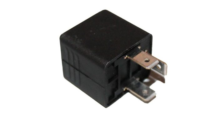
The lamps should work in a flashing mode. This requirement is related to the peculiarities of human perception - we better notice not the intensity (brightness) of the signal, but its change. Therefore, a flashing lantern attracts attention faster, even if it is visible in peripheral vision. In addition, it is more difficult to confuse it with position lamps or other lighting equipment. Intermittent lighting in the most modern cars is provided by electronic units, which include other operating functions. In the development machines of past years (and most of them), relay-breakers provide the flashing function.

How should a relay work?
The main requirement for a breaker relay is to generate an intermittent electrical signal with frequency 30-12 Hz for supplying turn signal lamps. Additional features are also desirable:
- control of the control lamp on the instrument panel;
- control of serviceability of lamp filaments;
- formation of a sound signal for audio control of the on state of the turn signals.
In breakers built on electromagnetic relays, the sound is obtained by itself - characteristic clicks occur during operation. In relays made on solid state keys, additional elements are provided for this function.
Wiring diagrams for turn signals on a car
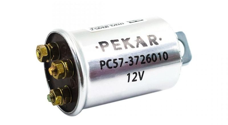
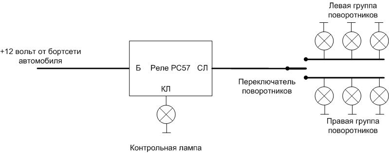
For the first mass-produced cars of the USSR, as well as for foreign cars of those years of production, the turn signal switching system was based on the RS57 electromagnetic thermal relay or similar. Such a relay is included in the break in the wire going to the turn signal lights. Lamps (6 pieces are installed on a passenger car) are connected in parallel into two groups of three lamps. The relay includes a temperature sensitive element, which is connected in series with the lamp filaments. A current flows through this circuit, heating the nichrome filament, which cyclically lengthens when heated and shortens when cooled. This ensures regular closing and opening of the power supply circuit of the lights. If one lamp burns out, then the current decreases, the flashing frequency increases. This serves as an indication of the failure of the lighting device.
Important! For this reason, the PC57 is problematic to use in conjunction with LED-based turn signals. Reduced current consumption will be perceived as an emergency.
It is also possible to connect a test lamp. It is installed on the instrument panel and repeats the state of the turn signal lights. The PC410 relay operates on the same principle, but it does not have a separate output for the control lamp.
The disadvantage of the interrupter is a short service life and a high level of heating during operation. Therefore, the relay is incapable of long-term switching on, and it is impossible to build an alarm on it - the device will quickly fail. Therefore, in more modern cars, an electronic relay is used - PC590 or its analogues. Several modifications of this device were produced.
| Relay | Application feature |
|---|---|
| PC590 | For vehicles with a trailer |
| RS590B | For vehicles without side turn signal repeaters |
| RS590K | For vehicles without a trailer |
| PC590E | For cars "Moskvich-2140" with a dual-mode signaling - when the dimensions are turned on (at night), the brightness of the turn signals decreased |
| RS590I | For Moskvich-2140 vehicles with dual-mode alarm and trailer |
| RS590P | For trailers |
The RS951 series of relays was also produced for cars with a 24 volt on-board network.
With the development of the range of electronic components, turn relays began to be built on a new basis, and the number of varieties has grown like an avalanche. So, one of the reference books on the device and repair of electronic devices in cars, published in 2003, contains more than 30 types of breakers. Their structural scheme is the same:
- master oscillator;
- power amplifier (relay or transistor);
- service schemes (monitoring the status of lamps, etc.).
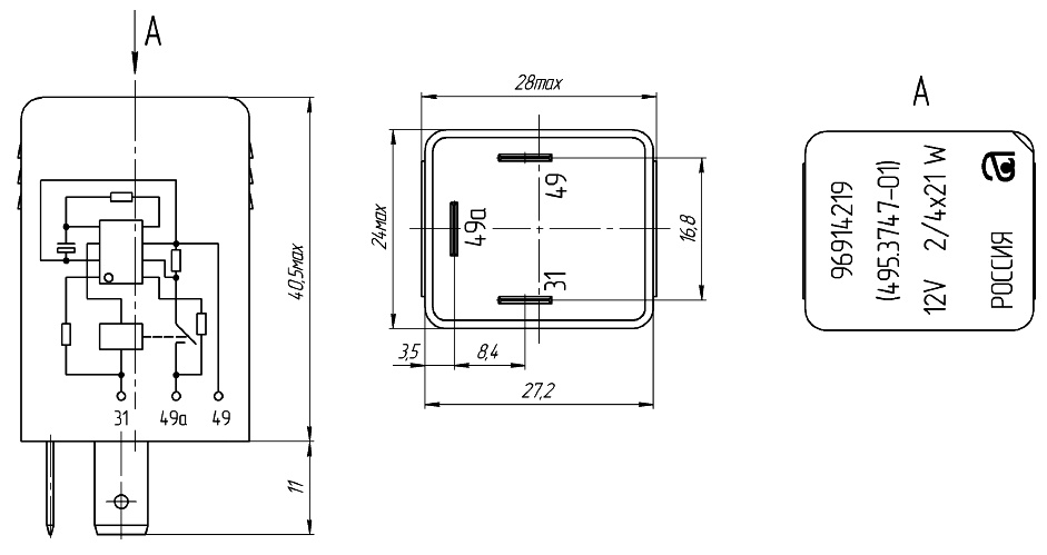
All devices are connected to the on-board network through alarm blocks. The generated pulses are fed through the turn signal switch to the lamps. For example, the diagram of turn signals on relay 495.3747 in the diagram of a VAZ-2110 car is shown.
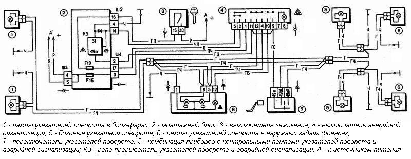
The interrupter is made on the basis of the UR1101XP32 microcircuit (a complete analogue of ASXP193, a functional analogue of U2043 from TEM1C).
The scheme for connecting turn signals through an electronic relay varies from car to car, to check the performance and replace faulty elements, it is necessary to analyze the electrical device of a particular machine.
Recommended for viewing: A simple two-component relay.
Turn relay pinout
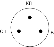
The location of the PC57 relay pins is shown in the figure. Terminal B is supplied with 12 volts from the vehicle's electrical system, a signal is taken from the SL terminal to the lamps. A control lamp is connected to the KL terminal.
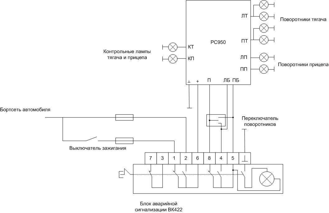
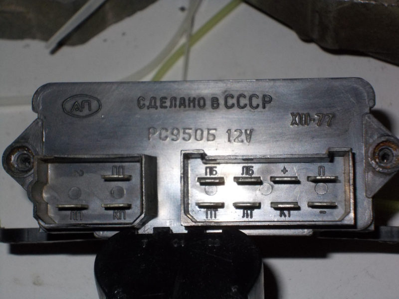
The PC950 has pin markings directly on the case. Sometimes, due to a layer of dust or dirt, it is not possible to read the symbols. In this case, you need to wipe the body of the device.
Read also: Headlight connection diagram via relay
Modern turn signal relays may have different pinouts, but still manufacturers strive for a single standard (with varying degrees of success). For such devices, it is better to specify the pinout in reference books.
According to the results of one of the surveys conducted by the traffic police, Approximately 20% of accidents were caused by the failure of turn signals. Keeping the turn signals in good condition and using them in cases stipulated by the traffic rules will reduce the likelihood of an accident by approximately the indicated figure.