Scheme of smooth ignition and attenuation of LEDs
gradual kindling LEDs Widely used in car electric tuning and advertising business to decorate banners. To implement this technique without the help of professionals, you can use one of the schemes, taking it on the Internet. If you can’t make a block yourself, you can purchase it at the store.
It is difficult to make a device for smooth turning on with your own hands without experience. It is necessary to understand the principle of operation of LEDs and electronic circuits. The advantage will be savings, since the cost of the manufactured device will be much lower than the cost of finished products.
On what principle does the circuit work?
For an inexperienced master, the smooth ignition and attenuation of LEDs may seem complicated, but it is not. In addition to simplicity, it is distinguished by reliability and low implementation costs.
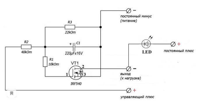
First, current is applied to the second resistor to charge the capacitor. C1. On the capacitor, the indicators do not change instantly, due to which the transistor opens smoothly VT1. Current is supplied to the gate through the first resistor. This provokes an increase in the potential (positive) on the field-effect transistor (its drain), due to which the LED turns on smoothly.
When a trip occurs, the capacitor will gradually discharge through the resistors. R1 and R3. The discharge rate is determined by the value of the third resistor.
Self-manufacturing
If you know all the details, it will take no more than 1 hour to work. It is necessary to select the necessary elements and equipment in order to make high-quality connections.
What you need
You will need:
- solder and soldering iron;
- LEDs;
- resistors;
- capacitor;
- transistors;
- housing to accommodate the necessary elements;
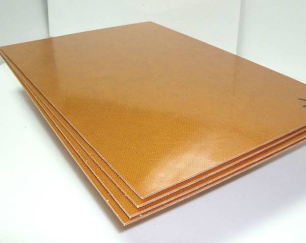
- a piece of textolite for the board.
Capacitor capacity - 220 mF. Voltage not more than 16 V. Resistors ratings:
- R1 - 12 kOhm;
- R2 - 22 kOhm;
- R3 - 40 kOhm.
When assembling, it is desirable to use an IRF540 field effect transistor.
Step-by-step instruction
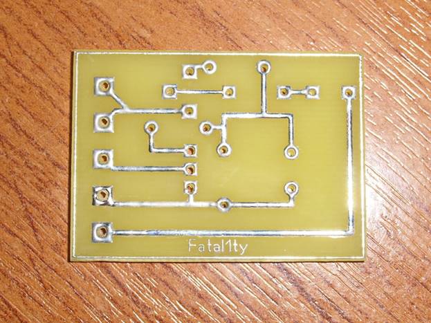
The first stage is the manufacture of the board. On the textolite, it is necessary to mark the boundaries and cut the sheet along the contours. Next, sand the workpiece with sandpaper (grit P 800-1000).
Next, print the circuit (layer with tracks). To do this, use a laser printer. The diagram can be found on the Internet. Sheet A4 is glued with masking tape to glossy paper (for example, from a magazine). Then the image is printed.
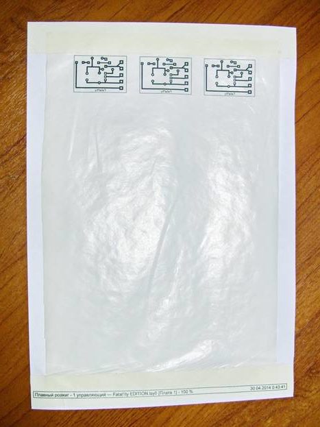
The scheme is glued onto the sheet, warming up with an iron. To cool the board, it must be placed in cold water for a few minutes, and then remove the paper. If it does not peel off immediately, it must be cleaned gradually.
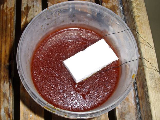
Use double-sided adhesive tape to glue the board to the foam of the same size and place it in a solution of ferric chloride for 5-7 minutes.In order not to overexpose the board, you need to periodically take it out and check the status. To speed up the etching process, you can shake the container with liquid. When excess copper is etched off, the board must be washed in water.
The next step is to clean the tracks with sandpaper and you can start drilling holes to install the board elements. Next, you need to pay the fee. To do this, it is lubricated with flux, after which it is tinned with a soldering iron. In order not to provoke overheating or open the circuit, the soldering iron must always be in motion.
The next step is to install the elements according to the scheme. To make it clearer, you can print the same diagram on paper, but with all the necessary symbols. After soldering, it is necessary to completely get rid of the flux. To do this, the board can be wiped with solvent 646, then cleaned with a toothbrush. When the block dries well, it needs to be checked. To do this, a constant plus and minus must be connected to the power supply. In this case, the manager plus should not be touched.
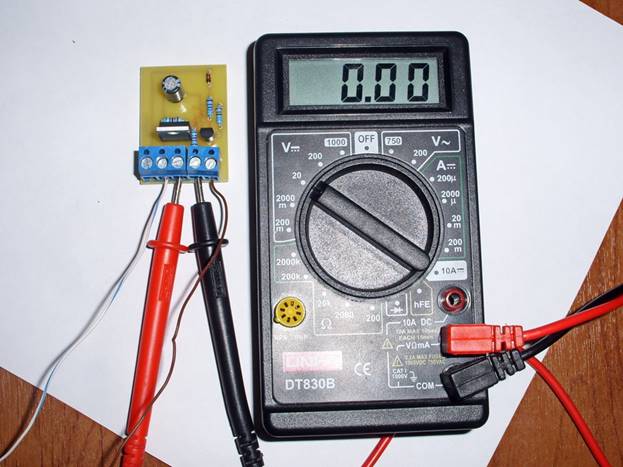
Instead of LEDs, it is better to use a multimeter for testing. If there is voltage, it means that the board is shorting. This may be due to flux residue. To get rid of the problem, just clean the board again. If there is no voltage, the unit is ready for use.
Features of the circuit with time setting
To be able to independently adjust the duration of turning off and on, resistors are added to the circuit.
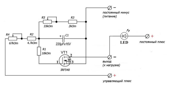
To smoothly turn on the LEDs, it is recommended to take resistors R3 and R2 of small ratings.The parameters of the resistors R4 and R5 make it possible to control the rate of attenuation and turn-on.
We recommend watching a series of thematic videos.
